This document serves to provide
users of the MErcury Surface, Space ENvironment, GEochemistry, and Ranging
(MESSENGER) Energetic Particle and Plasma Spectrometer (EPPS) data products
with a detailed description of the EPPS instrument, data product generation, validation,
and storage. Note that the EPPS is made up of two instrument subsystems, the
Fast Imaging Plasma Spectrometer (FIPS), and the Energetic Particle
Spectrometer (EPS). The FIPS and EPS are described in individual sections
within this document. They are referred to separately when necessary and
referred to as the EPPS instrument when dealing with areas common to both
instruments. The FIPS covers the lower energy range of particles and measures
the mass per charge (m/q), energy per charge (E/q), and incoming direction of
each charged particle. The EPS covers the higher energy range and measures
mass, energy, and incoming direction of each particle. The MESSENGER EPPS data
products are deliverables to the Planetary Data System (PDS) and the scientific
community that it supports. All data formats are based on the PDS standard.
The EPPS science data are divided into two categories: Level
2 edited raw data (referred to as experiment data records or EDRs) and
processed data (referred to as reduced data records or RDRs). RDRs are
generated from EDRs, and represent data calibrated to a physical unit such as
particle intensity (Level 3), resampled Level 4 data products, or derived Level
5 data products. RDRs consist of Calibrated Data Records (CDRs), Derived Data Records
(DDRs), and Derived Analysis Products (DAPs). This Software Interface
Specification (SIS) describes the EPPS DDR data products.
For EPS, DDRs consist of three products: pitch angle values,
pitch angle distribution spectrograms over selected ranges of energies for
selected time periods, and daily pitch angle distribution spectrograms. For
FIPS, DDRs consist of seven products that provide data for spatial and temporal
distributions of observed density for major ion species, and for selected ion
species and time periods, energy spectra, pitch angle distributions, ion flux,
density, temperature, and pressure, and viewing normalizations for each energy
scan. The DDR data were delivered to the PDS as CODMAC (Committee on Data
Management and Computation) Level 4 data. EPPS’s DDRs are formatted to include
standard PDS labels. A detailed description of all data products in the EPPS DDR
follows.
In addition, this SIS describes
the EPPS documentation volume, which contains products related to both the EDR-
and RDR-level archives. The contents of the documentation volume enables one to
conduct useful analysis of the DDRs. The documentation volume is described in
greater detail in section 6.6.
The MESSENGER EPPS SIS is
responsive to the following documents:
1.
Planetary Data System Standards
Reference, Feb 27, 2009, Version 3.8. JPL D-7669, Part-2.
2. MESSENGER Data Management and Archiving Plan. The Johns
Hopkins University, APL. Document ID number 7384-9019
3.
MESSENGER Mercury: Surface, Space
Environment, Geochemistry, Ranging; A mission to Orbit and Explore the Planet
Mercury, Concept Study, March 1999. Document ID number FG632/ 99-0479
4.
[PLR] Appendix 7 to the discovery
program Plan; Program Level Requirement for the MESSENGER Discovery project;
June 20, 2001.
The
following documents may be referenced for details on the EPPS instruments:
5. Livi et al., MESSENGER Energetic
Particle Spectrometer (EPPS/EPS) Calibration Report, 2004 (at PDS Geosciences
node: messgc_0001/EPS/EPS_CAL_RPT).
6.
Zurbuchen et
al. (The Fast Ion Plasma Spectrometer (FIPS) calibration report, MESSENGER
Project report, 2004)
- Andrews et al. (The Energetic Particle and Plasma
Spectrometer Instrument on the MESSENGER Spacecraft, Space Science Reviews
Volume 131, Numbers 1-4, August 2007)
- Raines et al.
(Distribution and compositional variations of plasma ions in Mercury’s
space environment: The first three Mercury years of MESSENGER
observations, Journal of Geophysical Research, 118, p1604-1619, 2013)
- Gilbert et al.
(Background noise in space-based time-of-flight sensors, Reviews of
Scientific Instrumentation, in review, 2014)
- Gershman
et al. (Post-processing modeling and removal of background noise in
space-based time-of-flight sensors, Deep Blue, 2013, http://hdl.handle.net/2027.42/100358)
- Raines et al.
(MESSENGER observations of the plasma environment near Mercury, Planetary
and Space Science 59, p2004-2015, 2011)
- Ho et al. (Spatial distribution and
spectral characteristics of energetic electrons in Mercury’s magnetosphere,
J. Geophys. Res., doi:10.1029/2012JA017983, 117, 2012)
- Gershman et
al. (Magnetic Flux Pile-up and Plasma Depletion in Mercury’s Subsolar
Magnetosheath, Journal of Geophysical Research: Space Physics, 118,
p7181-7199, 2013)
- Slavin et al. (MESSENGER Observations
of Extreme Loading and Unloading of Mercury’s Magnetic Tail, Science, 329,
p665-668, 2010, doi: 10.1126/science.1188067)
- Ho et al.
(Observations of Suprathermal Electrons in Mercury’s Magnetosphere during
the three MESSENGER Flybys, Planetary and Space Sci., 59, p2016-2025,
2011)
The EPPS DDR data products were
stored at the MESSENGER Science Operations Center (SOC) during the MESSENGER
mission. The data products were transferred to the PDS Planetary Plasma
Interactions (PPI) Node according to the delivery schedule in section 7. The data in the DDR files is stored in PDS ASCII TABLE
objects unless stated otherwise (section 5.2).
The roles and responsibilities of the instrument teams, The
Johns Hopkins University Applied Physics Laboratory (APL), Applied Coherent
Technology Corporation (ACT), and the Planetary Data System (PDS), are
discussed in sections 5.3.2 and 5.3.3.
The Fast Imaging Plasma
Spectrometer (FIPS) measures the energy per charge (E/q), time-of-flight (TOF),
and incident angles for plasma ions entering the sensor. Intensities, velocity
distributions, and mass per charge (m/q) distributions are derived from these
measurements and make up FIPS primary science data. These data are used to
understand the kinetic properties, angular distributions, and composition of
Mercury magnetospheric ions, and contribute to the characterization of the
planetary magnetic field.
Ions measured by FIPS pass through
an electrostatic analyzer (ESA), located at the entrance to the sensor; a post-acceleration
chamber between the output of the ESA and the carbon foil; and a time-of-flight
telescope. The ESA at the entrance to FIPS acts as a wide-angle lens for ions,
with a 1.4 sr field of view. It allows only ions with a specific E/q band to
enter through its output plane. This band is stepped through 64 values to
complete one measurement cycle (scan), nominally from 0.046-13.3 keV/e. FIPS is
normally operated in one of two stepping rates: one step per second (normal
mode), or one step per 100 milliseconds (burst mode). When delays due to high-voltage
ramp-ups are included, these result in cycle times of 64 sec and 8 sec,
respectively. The operation of FIPS is highly configurable via table upload. The
time spent in each step can, in principal, be set to arbitrary values,
different for each step (nominally set at 100ms/1s for burst/regular mode). Associated
with each E/q step is a deflection voltage, a threshold, a settling time, and
an integration (dwell) time.
Ions exit the output plane of the
ESA and are then accelerated in the post acceleration chamber. This
acceleration is done to give low-energy ions sufficient energy to penetrate the
carbon foil. The acceleration also helps to reduce energy straggling and
angular scattering – effects that cause degradation in mass resolution and
imaging. When ions exit the carbon foil, secondary electrons are liberated. These
electrons travel to the Start MCP (microchannel plate), providing a timing-start
signal and incident angle information via impact location on a position-sensing
anode. The ion then travels through the TOF chamber and strikes the Stop MCP,
providing a timing-stop signal and allowing computation of TOF. From E/q and
TOF, m/q can be computed. FIPS can measure species from H to Fe, 1-60 amu/e (or
higher).
Individual ions are identified in
FIPS data from their E/q and TOF measurements. A simple model is used to
predict the TOF range expected for each ion as a function of E/q, referred
to as the E/q-TOF track for that ion. This model includes the
effects of energy lost upon passage through the carbon foil, as well delays due
to electron flight time and electronic processing. All events with measured TOF
within the predicted range for a particular ion are assigned to that ion. To
improve signal to noise, E/q-TOF tracks for some ions are grouped
together. In this dataset, H+, He+, and He2+
are assigned from their respective individual ion tracks. Two ion groups are
defined: O+ group (m/q = 16 – 20; including O+ and
water group ions) and Na+ group (m/q = 21-30; including Na+,
Mg+, and Si+). Additional details concerning this process
are given in [8].
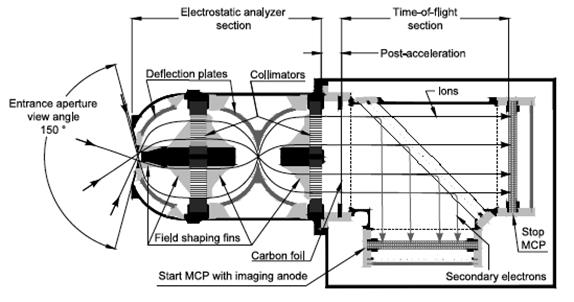
Figure 1 Cross-section of the FIPS sensor showing both the
ESA and TOF section [7]. Ions are analyzed by their energy per charge, 2D
position, and total time of flight.
FIPS uses a double coincidence technique to greatly reduce
background noise. However, spurious double-coincidence counts still do occur.
These counts come from two main sources: the extension of very high count
proton measurements into other times of flight, and the release of small
numbers ions from surface processes within the instrument [9]. While all major ion species reported here can be analyzed from the raw data, accuracy is
significantly improved by removing these spurious counts. A detailed noise
model and removal method has been developed [10] and is employed on the data in this work at the individual scan level.
After species are identified in E/q-TOF space and
noise counts removed, the resulting counts for species s (Ci,s)
at each measured (E/q)i are transformed to phase space
density (fi,s) in units of s3 m-6.
Using the CDR fluxes (Ji,s) in sec-1 cm-2 sr-1,
this conversion is achieved using the following relationship:

where vi,s is velocity, ms
is ion mass (in amu) and C is a unit conversion factor, 1.6022 × 10⁻²⁰
(cm2 s keV)-1 .
The details of the conversion of counts to phase space
density are provided in the EDR2CDR document, available in the CALIBRATION
directory of the EPPS documentation volume.
Details of FIPS operations can be
found in [7].
EPS is a compact TOF telescope with two main components: a
TOF section and a Solid State Detectors (SSD) array. The SSD array comprises
six ion-implanted planar silicon detectors, each with four pixels (two
dedicated to ion measurements and two to electron measurements) for a total of
24 SSD elements. Particles enter the system through a mechanical collimator
that delimits the look direction into the instrument. Particles that pass
through the collimator then transit through a thin, composite Start foil (polyimide
+ aluminum, 10 mg/cm2) and
onto the TOF region of the instrument.
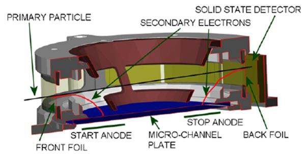
Figure 2 Cross-section of the EPS sensor. The particle tranverses
from left to right in the figure and terminates at the SSD. The primary
particle generates secondary electrons when it passes through both the front
and stop foil. These electrons are being steered toward the anodes at the
bottom of the figure.
Electrons are released from the inner surface of the Start
foil and focused to a well-defined region on an MCP to generate the START
signal in a dedicated anode. The incident ions are not significantly affected
by the electric fields of the focusing optics. After a 6 cm flight path, ions
traverse the Stop foil, which is a polyimide + palladium (19 mg/cm2) composite foil. The
secondary electrons released by the stop foil are steered to the MCP and
generate the STOP signal. Electron trajectory simulations show that there is
less than 2 ns dispersion in the transit time of the secondary electron from
the foil to the MCP. Sub-nanosecond dispersion is required so as not to
misidentify ion species. If both a START and STOP signal (double coincidence)
are registered, then the time, t, for the particle to travel a known
distance (d=6 cm) can be determined. For triple coincidence we must have
the START, STOP, and also the energy measured (Emeas) by the
SSDs. Using these measured parameters, we can calculate the mass (M) and
the incident energy (E) of each ion using the following equations:


Etrue takes into account the
small energy loss of the ions passing through the stop foil, and the energy
loss and pulse-height defect in the SSDs. EToF takes into
account the even smaller energy loss or gain in the start foil, and may also
include up to ~2.5 keV electrostatic pre-acceleration of ions that remain
charged on exiting the start foil. If the energy of the incident particle is
not large enough to trigger the SSD, then only t is measured and the
pulse height of the start anode is used to discriminate whether it is a light (M~1
amu), or heavy (M > 1 amu) ion. At the same value of TOF, heavy ions
have been shown to generate substantially more secondary electrons than do
protons.
Besides composition measurements, the particle’s angular
direction can be determined. The pair of start and stop anodes provide the
polar entrance angle of the incident particle. The polar angle of +80º to -80º is divided into six
equal sectors (nominally 27º).
Energetic electrons have higher penetration power than ions
at the same energy. The SSDs dedicated to electron detection in EPS are covered
by a thin layer (flashing) of 1mm of aluminum.
This dead layer stops protons with energy less then ~250 keV; Electrons, on the
other hand, lose less than 10 keV by the interaction with this dead layer.
Electrons are identified in EPS by the presence of an energy signal. The TOF
spectra collected in the adjacent SSD (without flashing) are used during ground
data analysis for checking and correcting for the proton contamination.
“Calibration” for a particle instrument like EPS means
determining the following:
- Transfer function from counts into flux (physical units)
- Characteristic of “Rate-out” versus “Rate-in”
- Response to low energy and high energy particle background
- Response to visible and ultraviolet light
- Response to high magnetic field
All these functions need to be characterized and the
relevant parameters need to be determined before flight.
Flux,
differential intensity, and phase space density
The number of particles N that traverse an area A during a
time t can be characterized by the flux F [1/cm2/s]
N= A * t * F
or by the intensity I [1/cm2/s/sr]
N= A * t * ò I cos(û) dW
where W is solid
angle and û is angle to the area normal. Here, the geometric characteristics of
the sensor determine the limits on the integration.
Often used is the quantity differential intensity f
[1/cm2/s/sr/keV], defined as the number of particles with energy between E and
E+ΔE that traverse the area A during the time t, where
N(E)=f(E) * A * t * DW *
ΔE
In three dimensions, with θ being the polar angle and
φ the azimuthal angle of a polar reference system:
d3N(E,θ,φ)=f(E, θ,
φ) * A cos(û) * t * dE cos θ dθ dφ
Note that f(E, θ, φ) is related to the phase-space
density psd (number of particles in the configuration space element d3R and
with velocity between v and v+ d3v) by the simple relationship in the
non-relativistic limit (valid for ions measured by EPS but not for the higher
energy electrons):
psd(s3/ cm6)=f(1/cm2/s/sr/keV) *
m/v2
For relativistic particles, one generally utilizes momentum
space rather than velocity space, and the corresponding expression is:
psd(s3/gm.cm6) = f(1/cm2/s/sr/keV)
/ p2
Where “p” is momentum.
Definition of sensor transfer function and geometric
factor
The number of counts N of particles of mass m, in the energy
band around mean energy E, angular band Δθ around mean polar
direction θ, and angular band Δφ around the mean azimuthal
direction φ, measured by the instrument during the time δt can be
expressed as:
N(E, θ, φ; m) = δt
* òΔE òΔθ òΔφ
f(E, θ, φ; m) * A cos(û) * dE cos θ dθ dφ
If f(E, θ, φ) is a Dirac δ function
(monoenergetic, infinitely narrow beam), then
N(E, θ, φ; m) = δt
* f(E, θ, φ; m) * G(E, θ, φ; m)
Where G(E, θ, φ; m) [cm2 sr keV] is the transfer
function of the instrument.
In the other limit, when the flux is completely isotropic
(all directions the same)
N(E; m) = δt * f(E; m) * GF(E;
m)
GF is called geometric factor. In this representation we
also include the species and energy dependence, which is a measure of the
efficiency of the system (count rate/flux), and typically is a function of
energy and species. Since the true geometric factor (or GF’) is only the
geometric mean (constant for energy and species) of the entrance system, we can
rewrite GF = GF’*e(E, m, θ, φ).
The goal of the calibration is to characterize the function
GF(E, θ, φ; m), so that from measurements of the count rates it is
possible to constrain f(E, θ, φ; m). Note that an exact inversion of
the integral is rarely possible, and we can compute only the coefficients of
some tailored expansion of f(E, θ, φ; m), such as in spherical
harmonics (Legendre polynomials). The accuracy of these coefficients depends on
both the raster coverage of the measurements and on the calibration.
5.1.2.3
Collimator
The EPS collimator consists of four concentric half circular
plates that have holes aligned with a common point of origin at the center of
the EPS TOF telescope. The size and number of collimator holes define the
geometric factor GF of the instrument. The many-holes collimator design
minimizes the scattering of ions and electrons at the collimator while
restricting the field-of-view (FOV) of the instrument.
GEANT4 simulation (which can stimulate the full GF(E,
θ, φ; m), not just the GF’) shows that the geometry factor for the
total SSD area to be 0.016 cm2 sr. The simulation accounted for gaps between
the detectors, but did not allow for the guard ring dead area between the large
and small pixels (~1mm wide) or the losses in the two grids used to mount the
thin foils. Hence, before grid losses, the total large pixel geometry factor is
therefore GFSSD = 0.0152 cm2 sr, and the small pixels would be 0.0008 cm2 sr. The
grid losses are actual blockages, so these should be included in the geometry
factor. EPS used 40-lines-per-inch grids on the foils that are 86% transmissive.
Therefore, for the 12 large pixels, we have a total geometry factor of
0.862x0.0152, or 0.011 cm2 sr, and each large pixel is 1/12 of that, or
GFSSD-Large = 0.001 cm2 sr. For the 12 small pixels, we have a total geometry
factor of 5.6x10⁻⁴ cm2 sr, or GFSSD-Small = 4.7x10⁻⁵ cm2 sr per pixel. The
current simulation does not model the scattering of low energy ion and electron
in the collimator; hence the current value of GFSSD is constant with energy and
look direction.
Disclaimer: EPS suffered a high-voltage failure shortly
after launch [15]; subsequently the TOF section never operated in flight.
Hence the following paragraph does not apply to the EPS flight data, we include
here for completeness only.
GFTOF for the Low Energy Ions (TOF-only) is roughly twice
the SSD values, or ~0.03 cm2 sr. Note that the needed Transfer Factor GF
depends also on the counting efficiency e
(E, m, θ, φ) which depends, in turn, on species and instrument mode.
However, these values were never conclusively determined. During the time of
instrument check out shortly after launch, EPS’s TOF section suffered a failure
[15]; subsequently, EPS lost its ability to measure ions by elemental mass
species. All in-flight EPS data contains null TOF values, hence, EPS can now
only measure
N(E) = δt * f(E) * GFSSD
GFSSD is now the geometric factor and represents a measure
of the efficiency of the system (count rate/flux), and is constant with look
direction, energy and species. This is the standard approximate conversion of
count rate to intensity assuming the channel efficiency is part of the geometry
factor. The shape of the energy spectrum also affects the response, here we
assume a monotonic energy spectra within the energy width of the channel.
The DDR data products generated by the EPS and FIPS
subsystems are described in this section. For all of the DDR products there is
a detached PDS label file, which describes the contents of one data file. Each
label file has the same base name as the data file it is describing, with the
extension “.LBL” to denote a label file. The label file defines the start time
and end of the observation, product creation time, and the structure of the
ASCII tables. Each data file contains the data collected on a given Earth day.
The
EPS portion of the data archive consists of tables of EPS pitch angle values, pitch
angle distribution function spectrograms in the form of browse plots, and daily
pitch angle distribution spectrograms in the form of browse plots
and text data files. These data products are derivate from the “Shaped” channel
on EPS which is an integrated (hardware) channel. The hardware channel
responded to all particles (ion and electron) that are above the threshold (~30
keV). Our experience at Mercury’s magnetosphere is that the primary particles
are mostly energetic electrons. Please note that the D03 detector on the EPS
has a very high background and is not useable for any of these science data
products.
5.2.1.1
Pitch Angle Computation
The pitch angle is defined as
the instantaneous angle between the particle flow direction and the measured
in-situ magnetic field, with 0 degrees being where the particle is traveling
along the field and 180 degrees where the particle is traveling in the opposite
direction. Both vectors (the particle flow direction and the magnetic field) are
measured in the spacecraft frame. The pitch angle values are calculated using
the EPS odd-shaped channels. These hardware channels correspond to ions or
electrons that are above the instrument threshold (nominally ~35 keV), and are
not affected by prioritization in the instrument software. For a rapidly
falling energy spectrum, these counts would be dominated at the lowest energies.
These values should be used in conjunction with the rate channels for which
intensity is computed. The particle flow direction for each of the six EPS look
directions is obtained by using the MESSENGER SPICE pointing kernels
(c-kernels) and the EPS frame kernel. The magnetic field measurements are taken
from MESSENGER Magnetometer (MAG) Level 1 1-second averaged data; see the MAG instrument
DDR SIS.
5.2.1.2
Pitch Angles Product
The pitch angle value tables
contain the pitch angle for each of the six look directions reported at the
same cadence as the EPS LoRes Spectral rate measurements (see EPPS CDR SIS document).
Each file thus has a one-to-one relationship with a corresponding LoRes
spectral file. Constant normalization factors and background subtractions have
been applied to these channels to offset any bias in the threshold setting. Channel
01 is set to be one and all other channels are normalized to that. The channel
chosen for normalization is arbitrary and does not impact the use of these data
products as they are supposed to be used in conjunction with the properly calibrated
rate channels. The formula used is Adjusted Value = Scaling * Raw Value +
Offset. The constant scaling and offset values are given in Table 2. Please note that the D03 detector on EPS has a
very high background and is not useable for any science data product.
5.2.1.3
Select Pitch Angle Distribution Spectrogram Product
The
pitch angle distribution shown in the pitch angle spectrogram browse plots
is plotted using the pitch angle values and time-averaged within the time
interval accordingly.
We
averaged the particle measurement in 120-second bins. Pitch angle bins are
22.5 degrees wide, and run from 0 to 180 degrees. For the pitch angle
distribution spectrogram, the color scale is normalized to the maximum counts for
the time interval covered by the current plot (i.e. the intensity color scale
varies between plots). The products provided in the
EPS_PITCH_ANGLES_SPECTROGRAM directory in this volume are selected based on the
criteria outlined by Ho et al. [JGR, 2012] on events that are at least 10 times
above the instrument background at the lowest energy channel 36-57 keV. Pitch
angle spectrogram products are provided for all orbital periods in the
EPS_PA_DAILY_SPECTROGRAM directory.
|
Channel Name
|
Scaling
|
Offset
|
|
SHAPED_COUNTS D00
|
1.0412691533565521
|
15.11127820611
|
|
SHAPED_COUNTS D01
|
1
|
0
|
|
SHAPED_COUNTS D02
|
0.7014738321304321
|
10.141375184059143
|
|
SHAPED_COUNTS D03
|
|
|
|
SHAPED_COUNTS D04
|
1.338530421257019
|
18.39651709794998
|
|
SHAPED_COUNTS D05
|
1.3527332693338394
|
7.795897737145424
|
|
SHAPED_COUNTS D06
|
1.4293411076068878
|
27.3230662047863
|
|
SHAPED_COUNTS D07
|
0.805070623755455
|
3.0807372108101845
|
|
SHAPED_COUNTS D08
|
0.9233275651931763
|
32.62595450878143
|
|
SHAPED_COUNTS D09
|
0.5404207110404968
|
-0.39973045140504837
|
|
SHAPED_COUNTS D10
|
0.31776440143585205
|
22.942654877901077
|
|
SHAPED_COUNTS D11
|
0.15649390034377575
|
-22.306587459519506
|
Table 2 Constant values used
to adjust the count rate for the shaped channels. D01 is the channel to which
all others were fit in order to arrive at these values, while D03 is unlike the
others and cannot be fit, so it remains unadjusted.
5.2.1.4
Daily Pitch Angle Distribution Spectrogram Product
The Daily Pitch angle Spectrogram products are similar to
the Select products described above, but are provided as daily products that
cover the entire orbital phase of the mission. Additionally, a text data file
(.TAB) accompanies each browse plot. The data file contains the same pitch
angle distributions as plotted in the browse product (.PNG), but as data
points.
Except where noted below, these data products are derived
from individual event (PHA) words, which have full angle and TOF information.
Using PHA words enables the finest possible separation into ion species as well
as distinguishing incident angles. Noise removal in E/q – TOF space is
performed before accumulation for all ions except H+, for which
noise removal is not needed.
The orbital regions for which data is provided varies by
product, as described below. Within these, data is provided for time steps
whenever the instrument was operating in a nominal mode and when the data was
of sufficient quality for scientific analysis. These conditions are met for
the vast majority of times throughout the mission. In particular, many of these
products are provided in regions determined by hand-picked or modeled bow shock
and magnetopause boundaries. Boundary picking was done by the MAG team at a
level of accuracy sufficient for the relatively low time resolution FIPS data
(10s - 60s). Where these were not available, the model given by Slavin et al.
[14] is used.
5.2.2.1
Differential Energy Flux Spectra
Differential energy flux spectra in units of (keV/e)-1 sec-1
cm-2 sr-1 are provided for all 5 ion species throughout
the entire magnetosphere and magnetosheath regions crossed by the spacecraft
during each orbit. These spectra cover the full energy per charge range of
FIPS, which ws 0.046 – 13.3 keV/e during most of the mission. See the FIPA_EYYYYDOY.DAT
file for exact energy range. They are derived in a manner completely analogous
to CDR differential energy flux spectra (dJi,s/dEi)
except that the total number of PHA event words for a given species at each E/q
step is used in place of on-board accumulated count rates (except protons).
See EPPS_FIPS_EDR2CDR.DOCX for more details.

For protons, this product is derived from on-board
accumulated rates just as for the CDR version, so that for protons only
this product is a duplicate of the CDR version. This duplication was intended
to allow users to primarily use DDR data only in their scientific analysis.
However, the differential energy spectra for protons only are not
organized according to the FIPA_EYYYYDOY.DAT files as are the rest of the ion
species in this product. The protons are instead organized by E/q step,
just as they are in the CDR version. Please refer to the EPPS CDR SIS for more
information. The CDR proton rate spectra product is also needed to determine
which of the available E/q tables to use for all species in this
product. This requirement to use CDR products in conjunction with their DDR
counterparts was unintended and will be removed in a future release.
5.2.2.2
Observed Density
Observed density (nobs,s, in cm-3)
for all ion species is provided for all 5 ion species throughout all orbit
regions. This product serves to determine the spatial and temporal distribution
of these ions and is the foundation DDR data product for FIPS. For protons,
this product is derived from on-board accumulated rates rather than PHA event
words, for much higher signal to noise ratio.
Observed densities are computed from differential energy
flux spectra Ji,s in two stages: First, dJi,s/dEi
is converted to phase-space density (fi,s, s3 m-6)

Second, fi,s integrated over all
velocities (vi,s) and solid angle (ΔΩ) for a full
scan to yield observed density (nobs,s) for species s

It is important to note that no correction has been made for
limited field of view in this calculation. This correction requires knowledge
of the true velocity distribution function in which the measured particles
reside and is therefore beyond the scope of this data product. The net result
is that nobs values reported are not in general equal to the ambient plasma
density. More information about calculation of nobs and the
limited FIPS field of view can be found in [10, 11].
5.2.2.3
Angular Flux Maps
Integrated ion flux, Js(θ,ϕ),
as a function of flow direction in MSO coordinates are provided for all 5 ion
species throughout the entire magnetosphere and magnetosheath regions crossed
by the spacecraft during each orbit. This product replaces the Arrival
Direction Histogram (ARRDIR) product as it more a more useful representation of
plasma behavior. Angular Flux Maps may be used in conjunction with pitch angle
distributions to understand the location and motion of ions relative to
Mercury. The discrete integration of phase space density (f) is
performed over ion speed (v) in the standard way, leaving the two
angular dimensions unchanged:

Very low count rates can make this product difficult to
interpret. For some ions, this situation is mitigated by summing over several,
often many, FIPS scans until sufficient counts are available. In other cases,
counts for a particular ion are so low the required number of counts would
require summation over large regions of space, making the arrival directions
again difficult to interpret. Therefore, these cases are not included in the
data.
Summing over multiple scans brings with it the need to
normalize the arrival direction distributions for the amount of time that a
particular incident angle could be observed. In normal operations, the
MESSENGER spacecraft rotates around the spacecraft Y-axis (YMSGR)
to optimize viewing for different instruments. FIPS orientation is fixed
relative to the spacecraft, so that the FIPS FOV rotates with the MESSENGER
spacecraft. This results in significant variation in observing time for look
directions in MSO coordinates. These variations in observing time have been
normalized out of the fluxes included in this data product. Despite this
normalization, the finite sensitivity of FIPS can still result in reduced
measured ion flux from arrival directions with low observing time. In
practice, this does not usually affect the typically qualitative interpretation
of these maps. The user could mitigate this effect by reducing the variability
of observing time: Only flux from directions that are viewed within a fixed
fraction (e.g. 0.1) of the maximum observation time for a given time
accumulation could be included in arrival direction histograms. This
restriction is not applied to delivered data from this data product.
The FLUXMAP data product is constructed and normalized as
follows:
- Two arrays representing a full 4π steradian FOV are
created at the 10° native angle binning of FIPS. This results in an 18 x
36 element array for the polar and azimuthal angle bins, respectively.
The first of these is used for the average flux, FLUX, while the second is
used for the average measurement time, VIEWTIME.
- The FLUX matrix for each energy scan is created from PHAs
as follows:
i.
Find the rotation matrix, ROTMSO, (described below) for the day
(YYYYDOY) and index which corresponds to the scan
ii.
Form the unit velocity vector:
1. Convert
the incident polar and azimuthal angles of the event from FIPS spherical
coordinates to FIPS Cartesian coordinates. Use the usual manner for spherical
to Cartesian conversion, using 1 for the r component.
2. Invert
the direction by multiplying all components by -1. This changes the FOV
coordinates to flow direction.
iii.
Rotate to MSO via multiplication by the ROTMSO.
iv.
Convert the resultant MSO vector to spherical coordinates. Round angles
down to the nearest 10°.
v.
Add the flux value multiplied by the PHA solid angle into a temporary 18
x 36 matrix using the rounded-down angles.
vi.
Convert entire FIPS spherical MCP map to MSO using the steps from (ii)
for each coordinate pair. Round angles down to the nearest 10°.
vii.
Add the MCP pixel solid angles into a second temporary 18 x 36 matrix
using the rounded-down angles.
viii.
Divide the temporary flux by the temporary solid angle,,
element-by-element.
- The VIEWTIME matrix for each energy scan is created as
follows:
i.
Calculate the average step measurement time for the scan
ii.
Add that value into every element of the VIEWTIME matrix
iii.
Set to 0 any matrix location for which the corresponding solid angle
matrix value is 0 (this will remove unobserved locations from the result).
- Sum FLUX and VIEWTIME over all accumulation scans
3. Form
the properly normalized product by dividing (element by element) the FLUX
(summed over scans) and VIEWTIME (summed over scans).

5.2.2.4
Arrival Direction (Retired Product)
This product class was retired after the Mercury Orbit Year
2 mission phase. The Angular Flux Map products described in the previous
section supersede it. Since the Arrival Direction products remain in version
V1.0 of the data set in the FIPS DDR archive volume at the PDS, a description
of them is retained in this document.
This product provides observed density as a function of
arrival direction in the instrument frame (incident polar and azimuthal angle) in
MSO coordinates for selected ions and regions around Mercury. The discrete
integration of phase space density (f) is performed in the velocity
dimension (v) only, leaving the two angular dimensions unchanged:

The above quantity, termed “observed density”, is analogous
to density in each angular bin formed only from the counts observed in that
bin. It differs from that performed in the Angular Flux Map product by one
power of v which introduced in that product to change from a density to
a flux quantity.
The Arrival Direction Histogram product is identical in
several ways to the Angular Flux Maps product that replaced it: It can be
difficult to interpret due to very low count rates, a problem which is
partially mitigated by summing over FIPS scans. This summing then requires
proper normalization, performed in exactly the same manner as described in
detail for Angular Flux Maps. This product may be used in conjunction with
pitch angle distributions to understand the location and motion of ions relative
to Mercury.
The ARRDIR data product is constructed and normalized exactly
as described above for the Angular Flux Maps, with two exceptions (with the
ARRDIR array replacing the FLUXMAP array):
- The velocity vector must NOT be inverted by reversing the
sign of each component.
- Multiply the weight from each PHA is added into the ARRDIR
array. It is not multiplied by the particle speed. (Modify
step 2.b.iv. above.)
5.2.2.5
Pitch Angle Distributions
For an ion in the presence of a magnetic field, the angle between
the velocity vector and the local magnetic field direction is referred to as
pitch angle. For populations of plasma ions, pitch angle distribution
histograms can be formed by counting the number of ions within a given pitch
angle range (PCHANG data product). This histogram may also be separated into
measured E/q bins, forming energy-resolved pitch angle distributions
(ERPCHANG data product). Pitch angle distributions give information on the
velocity of ions along magnetic field lines, character of velocity
distributions and the general plasma environment. Care must be taken when
interpreting pitch angle distributions in the instrument frame (such as these)
when the plasma has a non-negligible bulk velocity. Both the PCHANG and
ERPCHANG products are provided for all 5 ion species throughout the entire
magnetosphere and magnetosheath regions crossed by the spacecraft during each
orbit.
The pitch angle distribution for a given time period
consists of a histogram of these angles in 10° bins for all the ion events (PHA
words) in the time period. Energy-resolved pitch angle distributions are also
separated into the native FIPS E/q stepping bins. Pitch angle
distributions are provided for selected ions and time periods, when sufficient
statistics exist to make the product meaningful for scientific studies.
The PCHANG data product is normalized as follows:
- Two arrays representing pitch angles 0-180° are created at
10° binning, resulting in two 18-element arrays. The first of these is
used for the average flux, FLUX, while the second is used for viewing
normalization, VIEWTIME.
- The FLUX array for each energy scan is created from PHAs
as follows:
i.
Find the rotation matrix, ROTMSO, (described below) for the day
(YYYYDOY) and index which corresponds to the scan
ii.
Form the unit velocity vector:
1. Convert
the incident polar and azimuthal angles of the event from FIPS spherical
coordinates to FIPS Cartesian coordinates. Use the usual manner for spherical
to Cartesian conversion, using 1 for the r component.
2. Invert
by multiplying all components by -1. This changes the FOV coordinates to flow
direction.
iii.
Rotate to MSO via multiplication by the ROTMSO.
Average the MAG CDR vectors (already in MSO) that fall
within the FIPS scan time to one value
v.
Calculate the angular separation between this vector and the average MAG
vector. Round down angle to nearest 10°.
vi.
Add the flux value multiplied by the PHA solid angle into a temporary 18
element array using the rounded-down angles.
vii.
Convert entire FIPS spherical MCP map to MSO using the steps from (ii)
for each coordinate pair. Round angles down to the nearest 10°.
viii.
Calculate the angular separation between the MCP vectors and the average
MAG vector. Round down angle to nearest 10°.
ix.
Add the MCP pixel solid angles into a second temporary 18 element array
using the rounded-down angles.
x.
Divide the flux temp by the solid angle temp, element-by-element.
- The VIEWTIME array for each energy scan is created as
follows:
i.
Calculate the average step measurement time for the scan
ii.
Add that value into every element of the VIEWTIME array.
iii.
Set to 0 any array location for which the corresponding solid angle
array value is 0 (this will remove unobserved locations from the result).
- Sum FLUX and VIEWTIME over all accumulation scans
3. Form
the properly normalized product by dividing (element by element) the FLUX
(summed over scans) and VIEWTIME (summed over scans).

The ERPCHANG product is formed in an analogous fashion, with
the additional separation by E/q step. In this case, the weighting value
in the ‘FLUX’ numerator is average phase space density.
5.2.2.6
Kinetic Properties
Under several conditions, full number density, n, temperature,
T, and pressure, P, can be calculated directly from counts. (In
contrast, when these conditions are not fulfilled, only the partial, observed
densities, described above in 5.2.2.2, can be determined.) The conditions are
as follows:
1) There must
be sufficient counts to produce a well-defined energy spectrum. When necessary,
counts from multiple scans are summed to meet this criterion.
2) The plasma
must be subsonic. That is,

where vb is the
plasma bulk velocity and Vth is the plasma thermal velocity.
3) The plasma
must be nearly isotropic. That is,

where T⊥ is
the plasma temperature perpendicular to the magnetic field and T||
is the plasma temperature parallel to the magnetic field.
This data is provided where these assumptions are most
likely to hold: a) throughout the magnetosphere and b) the dayside
magnetosheath within a 45° cone angle around the XMSO axis.
Furthermore, the data are averaged over multiple FIPS scans so as to minimize
the effect on the recovered n and T of transients (e.g. high
speed flows) which violate the assumptions. However, for studies
involving features near the time scale of the averaged data and/or inside the
magnetosheath, users are strongly cautioned to evaluate the validity of
the assumptions themselves. This is most easily done by comparing velocity
distribution functions, computed from differential energy flux spectra and
averaged to the same period as this data, to those formed from a non-drifting
Maxwell-Boltzmann velocity distribution formed from the recovered n and T
(with bulk speed of zero).
For protons, this product is derived from on-board
accumulated rates rather than PHA event words, for much higher signal to noise
ratio. Data is summed over multiple scans to increase signal to noise.
Furthermore, this data is produced only those accumulations which exceed a
minimum count level (20 counts). Extensive testing has shown that computing
these products from PHA event words for ions heavier than protons is not
practical at fixed time steps of the order of a few minutes. Therefore, these
ions are not included in this product.
When these conditions are fulfilled, we compute n and
vth directly from measured velocity distribution
functions (formed from differential energy flux spectra) using a numerical
method of solving the system of moment equations [Gershman et al.,
2013]. T and P are then calculated using the usual relations:

where kb is the Boltzmann constant. The
units of the recovered plasma parameters are cm-3, MK, and nPa for
n, T, and P, respectively. The quoted uncertainties of these parameters are a
function of only number of counts used to create each distribution, following
Gershman et al., 2013. There are small additional uncertainties that result as
the measured energy spectra approach the limits of conditions (2) and (3) above.
These additional uncertainties are difficult to quantify and not included in
the reported uncertainties.
5.2.2.7
Viewing Normalization
The
FIPS Viewing Normalization data product contains a rotation matrix (ROTMSO)
from FIPS cartesian to MSO coordinates, for each FIPS energy scan. This matrix
can be used to rotate ion incident angles in CDR PHA data into MSO coordinates
needed for producing normalized directional maps (e.g. FLUXMAP or PCHANG) for
arbitrary time resolutions, in multiples of 10s.
There
is one EPPS PDS Documentation Archive Volume and one EPPS PDS Data Archive
Volume. The data volume contains level 4 CODMAC data products, also known as DDRs.
Each product has a unique file name and conforms to the file naming convention
in section 6.5. All DDR products were stored at the MESSENGER Science
Operations Center (SOC) during the MESSENGER mission. Volumes were transferred
to the PDS PPI Node following the procedure in section 5.3.3.
The EPPS DDR files were
produced by the EPS and FIPS teams. A Java program derived from the MIDL
(Mission Independent Data Layer) analysis software developed by APL was used to
generate the DDRs. The FIPS data were produced using Interactive Data Language
(IDL) software routines developed at the University of Michigan. The DDR data
products were made available to the MESSENGER Science Team for initial
evaluation and validation. At the end of the evaluation and validation period,
the data were organized and stored in the directory structure described in
section 6.8 for transfer to the PPI Node. The transmittal process is described
in section, 5.3.3. An initial release of the documentation volume accompanied
the initial release of the data volume. Thereafter, updates to the
documentation volume were made with each data delivery to document the data
quality for the delivery, changes to products including calibration updates,
and other updates as appropriate. PDS provides public access to the data
products through its online distribution system. These products support
engineering analysis, direct science analysis, and construction of other
science products.
The MESSENGER SOC operates under the auspices of the
MESSENGER Project Scientist to plan data acquisition, generate, and validate
data archives. The SOC supports and works with the Mission Operations Center (MOC),
the Science Team, instrument scientists, and the PDS.
Figure 1 MESSENGER data flow shows the flow of data within the MESSENGER project and out to PDS. The MOC
handles raw data flow to and from the MESSENGER spacecraft and the SOC converts
the raw telemetry into EDRs, which are subsequently converted into CDRs and
DDRs by the Science Team. Documentation, CDRs, and DDRs are delivered to the
PDS Planetary Plasma Interactions (PPI) node. All SPICE kernels used in CDR and
DDR processing are delivered to the PDS Navigation and Ancillary Information
(NAIF) node. The delivery process is detailed below.
The MESSENGER SOC delivered data for the EPPS DDR data
volume to the PDS PPI Node in standard product packages. Each package comprises
data and ancillary data files, organized into directory structures consistent
with the volume design described in section 6.8. The initial release contained
the documents and required files for the EPPS documentation volume, organized
into directory structures as described in section 6.7. Subsequent releases to
the EPPS documentation volume contained updates as appropriate.
In preparation for delivery, the directory structure is
compressed into a single “zip archive” file for transfer to the PDS node. The
zip archive preserves the directory structure internally so that it can be
recreated after delivery to the PDS node. Also included in the transfer is a
checksum file created using the MD5 algorithm. This provides an independent
method of verifying the integrity of the zip file after it has been sent.
Within days of receipt of the delivery the PDS node acknowledges receipt of the
archive and checksum file. If acknowledgement is not received, or if problems
are reported, the MESSENGER SOC immediately takes corrective action to affect
successful transfer. Delivery size determines the transfer mechanism:
electronic or shipping a hard drive.
The PDS node uncompresses the zip archive file and checks
for data integrity using the checksum file. The node performs any additional
verification and validation of the data provided and reports any discrepancies
or problems to the MESSENGER SOC. The node performs these checks within about
two weeks from receipt of the delivery. After inspection has been completed to
the satisfaction of the PDS node, the node issues an acknowledgement of
successful receipt of the data to the MESSENGER SOC.
Following receipt of a data delivery the PDS node organizes
the data into a PDS volume archive structure within its online data system.
Newly delivered data are made available publicly from PDS once accompanying
labels and other documentation have been validated.
5.3.4
Labeling and Identification
The PDS label conforms to PDS version 3.8 standards. For
more information about this standard consult the PDS Standards Reference
Document. The label is detached and in a separate PDS label file. The purpose
of the PDS label is to describe the data product and provide ancillary
information about the data product. There is a PDS label file for every EPPS DDR
data file. There is one DATA_SET_ID assigned to the EPPS DDR data. The DDRs are
further grouped into data products and are identified by the
STANDARD_DATA_PRODUCT_ID keyword and the file naming convention, section 6.5. Example label file content is shown here for every DDR data product. Note that
the data are contained within an ASCII table and the details of the table
structure are described by an external ASCII format file (*.FMT). The columns
in each format file are described separately in the Appendix.
5.3.4.1
EPS Pitch Angles Label
A sample EPS Pitch Angles DDR file label is shown below:
PDS_VERSION_ID
= "PDS3"
/* ** FILE
FORMAT ** */
FILE_RECORDS
= 5798
RECORD_TYPE
= FIXED_LENGTH
RECORD_BYTES
= 167
/* **
GENERAL DATA DESCRIPTION PARAMETERS ** */
PRODUCT_ID
= "EPSP_A2012010DDR_V1"
PRODUCT_VERSION_ID
= "V1"
PRODUCT_CREATION_TIME
= 2012-05-09T21:04:27
PRODUCT_TYPE
= "DDR"
STANDARD_DATA_PRODUCT_ID
= "EPS_PITCH_ANGLES_DDR"
SOFTWARE_NAME
= "MIDLMessengerDDRGenerator"
SOFTWARE_VERSION_ID
= "1.0"
INSTRUMENT_HOST_NAME
= "MESSENGER"
INSTRUMENT_NAME
= "ENERGETIC PARTICLE SPECTROMETER"
INSTRUMENT_ID
= "EPS"
DATA_SET_ID
= "MESS-E/V/H/SW-EPPS-3-EPS-DDR-V1.0"
DATA_SET_NAME
= "MESSENGER E/V/H/SW EPPS CALIBRATED EPS DDR
V1.0"
MISSION_PHASE_NAME
= "MERCURY ORBIT"
TARGET_NAME
= "MERCURY"
START_TIME
= 2012-010T00:00:49
STOP_TIME
= 2012-010T23:59:45
SPACECRAFT_CLOCK_START_COUNT
= "234641115"
SPACECRAFT_CLOCK_STOP_COUNT
= "234727451"
^HEADER
= ("EPSP_A2012010DDR_V1.TAB", 1)
^ASCII_TABLE
= ("EPSP_A2012010DDR_V1.TAB", 2)
OBJECT
= HEADER
HEADER_TYPE = TEXT
INTERCHANGE_FORMAT = "ASCII"
RECORDS = 1
BYTES = 167
DESCRIPTION = "The first record of this
file is
the header section. The header contains column
headings
to improve usability."
END_OBJECT
= HEADER
OBJECT
= ASCII_TABLE
COLUMNS = 7
INTERCHANGE_FORMAT = ASCII
ROW_BYTES = 167
ROWS = 5798
DESCRIPTION
= "
This
table contains Pitch Angles between the measured flow vector
direction and the magnetic field for each of the 6 sectors of
the
MESSENGER EPS instrument. The complete column definitions are
contained in an external file found in the LABEL directory of the
archive
volume. Additional details are contained in the DDR SIS
document."
NOTE = "Data Quality: 0"
^STRUCTURE = "EPS_PITCH_ANGLES.FMT"
END_OBJECT
= ASCII_TABLE
END
5.3.4.2
EPS Select Pitch Angle Spectrogram Label
A sample EPS Select Pitch Angle Spectrogram DDR file label
is shown below:
PDS_VERSION_ID
= "PDS3"
/* ** FILE
FORMAT ** */
RECORD_TYPE
= UNDEFINED
INTERCHANGE_FORMAT
= BINARY
/* **
GENERAL DATA DESCRIPTION PARAMETERS ** */
PRODUCT_ID
= "EPS_PAS_2012074205045_V1"
PRODUCT_VERSION_ID
= "V1"
PRODUCT_CREATION_TIME
= 2012-05-09T17:00:00
PRODUCT_TYPE
= "BROWSE"
STANDARD_DATA_PRODUCT_ID
= "EPS_PITCH_ANGLE_SPECTROGRAM_DDR"
SOFTWARE_NAME
= "MIDLMessengerDDRGenerator"
SOFTWARE_VERSION_ID
= "1.0"
INSTRUMENT_HOST_NAME
= "MESSENGER"
INSTRUMENT_NAME
= "ENERGETIC PARTICLE SPECTROMETER"
INSTRUMENT_ID
= "EPS"
DATA_SET_ID
= "MESS-E/V/H/SW-EPPS-3-EPS-DDR-V1.0"
DATA_SET_NAME =
"MESSENGER E/V/H/SW EPPS CALIBRATED EPS DDR V1.0"
MISSION_PHASE_NAME
= "MERCURY ORBIT"
TARGET_NAME
= "MERCURY"
START_TIME
= 2012-03-14T20:50:45
STOP_TIME
= 2012-03-15T00:23:45
SPACECRAFT_CLOCK_START_COUNT
= "240245710"
SPACECRAFT_CLOCK_STOP_COUNT
= "240258490"
^DOCUMENT
= "EPS_PAS_2012074205045_V1.PNG"
OBJECT
= DOCUMENT
DOCUMENT_NAME = "EPS_PAS_2012074205045_V1"
DOCUMENT_FORMAT = PNG
DOCUMENT_TOPIC_TYPE = "BROWSE IMAGE"
INTERCHANGE_FORMAT = BINARY
PUBLICATION_DATE = 2012-05-09T17:00:00
SOURCE_PRODUCT_ID = {
"EPSL_R2012074EDR_V1.DAT",
"MAGSC_SCIAVG12075_01_V00.TAB",
"MAGSC_SCIAVG12074_01_V00.TAB",
"EPSL_R2012075EDR_V1.DAT"
}
LINES = 400
LINE_SAMPLES = 850
SAMPLE_TYPE = MSB_UNSIGNED_INTEGER
SAMPLE_BITS = 8
DESCRIPTION = "PNG file containing a spectrogram representation of
the summation of the shaped count rates in detectors 0-10 except detector 3. The
counts are binned in time (120 s) and pitch angle (22.5 deg). Constant
normalization factors and background subtractions (see SIS for Table) have been
applied to these rates."
END_OBJECT
= DOCUMENT
END
5.3.4.3
EPS Daily Pitch Angle Spectrogram Plot Label
A sample EPS Daily Pitch Angle Spectrogram Plot DDR file
label is shown below:
PDS_VERSION_ID = "PDS3"
/* ** FILE FORMAT ** */
RECORD_TYPE = UNDEFINED
INTERCHANGE_FORMAT = BINARY
/* ** GENERAL DATA DESCRIPTION PARAMETERS ** */
PRODUCT_ID =
"EPS_PASD_IMAGE_2014100_DDR_V01"
PRODUCT_VERSION_ID = "V1"
PRODUCT_CREATION_TIME = 2017-005T16:43:05
PRODUCT_TYPE = "BROWSE"
STANDARD_DATA_PRODUCT_ID = "EPS_PA_SPEC_DDR"
SOFTWARE_NAME =
"MIDLMESSENGERDDRGENERATOR"
SOFTWARE_VERSION_ID = "1.0"
INSTRUMENT_HOST_NAME = "MESSENGER"
INSTRUMENT_NAME = "ENERGETIC PARTICLE AND PLASMA
SPECTROMETER"
INSTRUMENT_ID = "EPPS"
DATA_SET_ID =
"MESS-E/V/H/SW-EPPS-3-EPS-DDR-V1.0"
DATA_SET_NAME = "MESSENGER E/V/H/SW EPPS
CALIBRATED EPS DDR V1.0"
MISSION_PHASE_NAME = "MERCURY ORBIT"
TARGET_NAME = "MERCURY"
START_TIME = 2014-04-10T00:00:00
STOP_TIME = 2014-04-10T23:59:59
SPACECRAFT_CLOCK_START_COUNT = "2/039411999"
SPACECRAFT_CLOCK_STOP_COUNT = "2/039498398"
^DOCUMENT =
"EPS_PASD_IMAGE_2014100_DDR_V01.PNG"
OBJECT = DOCUMENT
DOCUMENT_NAME =
"EPS_PASD_IMAGE_2014100_DDR_V01"
DOCUMENT_FORMAT = PNG
DOCUMENT_TOPIC_TYPE = "BROWSE IMAGE"
INTERCHANGE_FORMAT = BINARY
PUBLICATION_DATE = 2017-01-09
SOURCE_PRODUCT_ID = {
"EPSL_R2014100EDR_V1.DAT",
"MAGSC_SCIAVG14100_01_V08.TAB",
"EPSL_R2014101EDR_V1.DAT"
}
LINES = 400
LINE_SAMPLES = 850
SAMPLE_TYPE = MSB_UNSIGNED_INTEGER
SAMPLE_BITS = 8
DESCRIPTION = "
PNG file containing a spectrogram representation of the
summation
of the shaped count rates in detectors 0-10 except
detector 3. The
counts are binned in time (120 s) and pitch angle (22.5
deg).
Constant normalization factors and background subtractions
(see SIS for Table) have been applied to these
rates."
END_OBJECT = DOCUMENT
END
5.3.4.4
EPS Daily Pitch Angle Spectrogram Data Label
A sample EPS Daily Pitch Angle Spectrogram data DDR file
label is shown below:
PDS_VERSION_ID = "PDS3"
RECORD_TYPE = "FIXED_LENGTH"
RECORD_BYTES = 406
FILE_RECORDS = 720
PRODUCT_ID = "EPS_PASD_NUMERIC_2014100_DDR_V01"
PRODUCT_VERSION_ID = "1"
PRODUCT_CREATION_TIME = 2017-005T16:43:05
PRODUCT_TYPE = "DDR"
STANDARD_DATA_PRODUCT_ID = "EPS_PASD_NUMERIC_DDR"
SOFTWARE_NAME = "EPSDAILYPITCHANGLEPDSCSVFILEWRITER"
SOFTWARE_VERSION_ID = "1.0"
INSTRUMENT_HOST_NAME = "MESSENGER"
INSTRUMENT_NAME = "ENERGETIC PARTICLE AND
PLASMA SPECTROMETER"
INSTRUMENT_ID = "EPPS"
DATA_SET_ID = "MESS-E/V/H/SW-EPPS-3-EPS-DDR-V1.0"
DATA_SET_NAME = "MESSENGER E/V/H/SW EPPS CALIBRATED EPS DDR
V1.0"
MISSION_PHASE_NAME = "MERCURY ORBIT YEAR 4"
TARGET_NAME = "MERCURY"
SOURCE_PRODUCT_ID = {
"EPSL_R2014100EDR_V1.DAT",
"MAGSC_SCIAVG14100_01_V08.TAB",
"EPSL_R2014101EDR_V1.DAT"
}
START_TIME = 2014-04-10T00:00:00
STOP_TIME = 2014-04-10T23:59:58
SPACECRAFT_CLOCK_START_COUNT = "2/039411999"
SPACECRAFT_CLOCK_STOP_COUNT = "2/039498398"
^HEADER =
("EPS_PASD_NUMERIC_2014100_DDR_V01.TAB", 1)
^ASCII_TABLE = ("EPS_PASD_NUMERIC_2014100_DDR_V01.TAB",
2)
OBJECT = HEADER
HEADER_TYPE = TEXT
INTERCHANGE_FORMAT = "ASCII"
RECORDS = 1
BYTES = 406
DESCRIPTION = "The first record of this
file is the header
section. The header contains column headings to improve
usability."
END_OBJECT = HEADER
OBJECT = ASCII_TABLE
COLUMNS = 17
INTERCHANGE_FORMAT = ASCII
ROW_BYTES = 406
ROWS = 720
DESCRIPTION = "The table contains
charged particle rate
data from the MESSENGER EPS instrument binned by Pitch
Angle."
^STRUCTURE =
"EPS_PASD_NUMERIC_DDR.FMT"
END_OBJECT = ASCII_TABLE
END
5.3.4.5
FIPS Pitch Angles Label (PCHANG)
A sample FIPS Pitch Angles DDR file label is shown below:
PDS_VERSION_ID
= "PDS3"
/* ** FILE FORMAT
** */
FILE_RECORDS
= 1350
RECORD_TYPE
= FIXED_LENGTH
RECORD_BYTES
= 2799
/* **
GENERAL DATA DESCRIPTION PARAMETERS ** */
PRODUCT_ID
= "FIPS_PCHANG_2012001_DDR_V01"
PRODUCT_VERSION_ID
= "V1"
PRODUCT_CREATION_TIME
= 2012-05-08T23:35:42
PRODUCT_TYPE
= "DDR"
STANDARD_DATA_PRODUCT_ID
= "FIPS_PCHANG_DDR"
SOFTWARE_NAME
= "mfips_decode_pha.pro"
SOFTWARE_VERSION_ID
= "1.0"
INSTRUMENT_HOST_NAME
= "MESSENGER"
INSTRUMENT_NAME
= "FAST IMAGING PLASMA SPECTROMETER"
INSTRUMENT_ID
= "FIPS"
DATA_SET_ID
= "MESS-E/V/H/SW-EPPS-3-FIPS-DDR-V2.0"
DATA_SET_NAME =
"MESSENGER E/V/H/SW EPPS CALIBRATED FIPS DDR V2.0"
SOURCE_PRODUCT_ID
= "FileByFile"
MISSION_PHASE_NAME
= "MERCURY ORBIT"
TARGET_NAME
= "MERCURY"
START_TIME
= 2012-01-01T00:00:00
STOP_TIME
= 2012-01-01T23:59:59
SPACECRAFT_CLOCK_START_COUNT
= "233863466"
SPACECRAFT_CLOCK_STOP_COUNT
= "233949802"
^HEADER
= ("FIPS_PCHANG_2012001_DDR_V01.TAB", 1)
^ASCII_TABLE
= ("FIPS_PCHANG_2012001_DDR_V01.TAB", 4)
OBJECT
= HEADER
HEADER_TYPE = TEXT
INTERCHANGE_FORMAT = "ASCII"
RECORDS = 3
BYTES = 8397
DESCRIPTION = "The first 3 records of
this
file are
the header section. The header contains column
headings
to improve usability."
END_OBJECT
= HEADER
OBJECT
= ASCII_TABLE
COLUMNS
= 3
INTERCHANGE_FORMAT = ASCII
ROW_BYTES = 2799
ROWS = 1350
DESCRIPTION = "
This
table contains FIPS Flux-Pitch angle histograms."
^STRUCTURE = "FIPS_PCHANG_DDR.FMT"
END_OBJECT
= ASCII_TABLE
END
5.3.4.6
Energy-Resolved Pitch Angle Distributions (ERPCHANG) Label
A sample FIPS ERPCHANG DDR file label is shown below:
PDS_VERSION_ID = "PDS3"
/* ** FILE FORMAT ** */
FILE_RECORDS = 5
RECORD_TYPE = FIXED_LENGTH
RECORD_BYTES = 16218
/* ** GENERAL DATA DESCRIPTION PARAMETERS ** */
PRODUCT_ID = "FIPS_ERPCHANG_2011174_V1"
PRODUCT_VERSION_ID = "1"
PRODUCT_CREATION_TIME = 2014-11-06T16:00:00
PRODUCT_TYPE = "DDR"
STANDARD_DATA_PRODUCT_ID = "FIPS_ERPCHANG"
SOFTWARE_NAME =
"MFIPS_DDR_SAMPLE.PRO"
SOFTWARE_VERSION_ID = "0.1"
INSTRUMENT_HOST_NAME = "MESSENGER"
INSTRUMENT_NAME = "ENERGETIC PARTICLE AND
PLASMA SPECTROMETER"
INSTRUMENT_ID = "EPPS"
DATA_SET_ID =
"MESS-E/V/H/SW-EPPS-3-FIPS-DDR-V2.0"
DATA_SET_NAME = "MESSENGER E/V/H/SW EPPS
CALIBRATED FIPS DDR
V2.0"
MISSION_PHASE_NAME = "MERCURY ORBIT"
TARGET_NAME = "MERCURY"
START_TIME = 2011-06-23T10:45:40.419666
STOP_TIME = 2011-06-23T22:53:43.420605
SPACECRAFT_CLOCK_START_COUNT = "1/217313408.800"
SPACECRAFT_CLOCK_STOP_COUNT = "1/217357091.000"
^HEADER =
("FIPS_ERPCHANG_2011174_DDR_V01.TAB", 1)
^ASCII_TABLE = ("FIPS_ERPCHANG_2011174_DDR_V01.TAB",
4)
OBJECT = HEADER
HEADER_TYPE = TEXT
INTERCHANGE_FORMAT = "ASCII"
RECORDS = 3
BYTES = 48654
DESCRIPTION = "The first four records of
this
file are the header section. The header contains column
headings to improve usability."
END_OBJECT = HEADER
OBJECT = ASCII_TABLE
COLUMNS = 7
INTERCHANGE_FORMAT = ASCII
ROW_BYTES = 16218
ROWS = 2
DESCRIPTION = "
This table contains 2 dimensional pitch angle histograms as
described in EPPS DDR SIS."
^STRUCTURE =
"FIPS_ERPCHANG_DDR.FMT"
END_OBJECT = ASCII_TABLE
END
5.3.4.7
FIPS Energy Spectra Label
A sample FIPS Energy Spectra DDR file label is shown below:
PDS_VERSION_ID = "PDS3"
/* ** FILE
FORMAT ** */
FILE_RECORDS
= 1350
RECORD_TYPE
= FIXED_LENGTH
RECORD_BYTES
= 4824
/* **
GENERAL DATA DESCRIPTION PARAMETERS ** */
PRODUCT_ID
= "FIPS_ESPEC_2012001_DDR_V01"
PRODUCT_VERSION_ID
= "V1"
PRODUCT_CREATION_TIME
= 2012-05-08T23:35:41
PRODUCT_TYPE
= "DDR"
STANDARD_DATA_PRODUCT_ID
= "FIPS_ESPEC_DDR"
SOFTWARE_NAME
= "mfips_decode_pha.pro"
SOFTWARE_VERSION_ID
= "1.0"
INSTRUMENT_HOST_NAME
= "MESSENGER"
INSTRUMENT_NAME
= "FAST IMAGING PLASMA SPECTROMETER"
INSTRUMENT_ID
= "FIPS"
DATA_SET_ID
= "MESS-E/V/H/SW-EPPS-3-FIPS-DDR-V2.0"
DATA_SET_NAME =
"MESSENGER E/V/H/SW EPPS CALIBRATED FIPS DDR V2.0"
SOURCE_PRODUCT_ID
= "FileByFile"
MISSION_PHASE_NAME
= "MERCURY ORBIT"
TARGET_NAME
= "MERCURY"
START_TIME
= 2012-01-01T00:00:00
STOP_TIME
= 2012-01-01T23:59:59
SPACECRAFT_CLOCK_START_COUNT
= "233863466"
SPACECRAFT_CLOCK_STOP_COUNT
= "233949802"
^HEADER
= ("FIPS_ESPEC_2012001_DDR_V01.TAB", 1)
^ASCII_TABLE
= ("FIPS_ESPEC_2012001_DDR_V01.TAB", 4)
OBJECT
= HEADER
HEADER_TYPE = TEXT
INTERCHANGE_FORMAT = "ASCII"
RECORDS = 3
BYTES = 19094472
DESCRIPTION = "The first 3 records of
this
file are
the header section. The header contains column
headings
to improve usability."
END_OBJECT
= HEADER
OBJECT
= ASCII_TABLE
COLUMNS = 7
INTERCHANGE_FORMAT = ASCII
ROW_BYTES = 4824
ROWS = 1350
DESCRIPTION = "
This
table contains FIPS energy spectra for selected ion species."
^STRUCTURE = "FIPS_ESPEC_DDR.FMT"
END_OBJECT
= ASCII_TABLE
END
5.3.4.8
FIPS Observed Density Label
A sample FIPS Observed Density DDR file label is shown
below:
PDS_VERSION_ID
= "PDS3"
/* ** FILE
FORMAT ** */
FILE_RECORDS
= 1350
RECORD_TYPE
= FIXED_LENGTH
RECORD_BYTES
= 216
/* **
GENERAL DATA DESCRIPTION PARAMETERS ** */
PRODUCT_ID
= "FIPS_NOBS_2012001_DDR_V01"
PRODUCT_VERSION_ID
= "V1"
PRODUCT_CREATION_TIME
= 2012-05-08T23:35:42
PRODUCT_TYPE
= "DDR"
STANDARD_DATA_PRODUCT_ID
= "FIPS_NOBS_DDR"
SOFTWARE_NAME
= "mfips_decode_pha.pro"
SOFTWARE_VERSION_ID
= "1.0"
INSTRUMENT_HOST_NAME
= "MESSENGER"
INSTRUMENT_NAME
= "FAST IMAGING PLASMA SPECTROMETER"
INSTRUMENT_ID
= "FIPS"
DATA_SET_ID
= "MESS-E/V/H/SW-EPPS-3-FIPS-DDR-V2.0"
DATA_SET_NAME =
"MESSENGER E/V/H/SW EPPS CALIBRATED FIPS DDR V2.0"
SOURCE_PRODUCT_ID
= "FileByFile"
MISSION_PHASE_NAME
= "MERCURY ORBIT"
TARGET_NAME
= "MERCURY"
START_TIME
= 2012-01-01T00:00:00
STOP_TIME
= 2012-01-01T23:59:59
SPACECRAFT_CLOCK_START_COUNT
= "233863466"
SPACECRAFT_CLOCK_STOP_COUNT
= "233949802"
^HEADER
= ("FIPS_NOBS_2012001_DDR_V01.TAB", 1)
^ASCII_TABLE
= ("FIPS_NOBS_2012001_DDR_V01.TAB", 4)
OBJECT
= HEADER
HEADER_TYPE = TEXT
INTERCHANGE_FORMAT = "ASCII"
RECORDS = 3
BYTES = 648
DESCRIPTION = "The first 3 records of
this
file are
the header section. The header contains column
headings
to improve usability."
END_OBJECT
= HEADER
OBJECT
= ASCII_TABLE
COLUMNS = 20
INTERCHANGE_FORMAT = ASCII
ROW_BYTES = 216
ROWS = 1350
DESCRIPTION = "
This
table contains FIPS differential energy intensities for selected ion
species."
^STRUCTURE = "FIPS_NOBS_DDR.FMT"
END_OBJECT
= ASCII_TABLE
END
5.3.4.9
FIPS Arrival Direction Label (Retired Product)
A sample FIPS Arrival Direction DDR file label is shown
below:
PDS_VERSION_ID = "PDS3"
/* ** FILE FORMAT ** */
FILE_RECORDS = 42
RECORD_TYPE = FIXED_LENGTH
RECORD_BYTES = 9158
/* ** GENERAL DATA DESCRIPTION PARAMETERS ** */
PRODUCT_ID = "FIPS_ARRDIR_2012054_DDR_V01"
PRODUCT_VERSION_ID = "01"
PRODUCT_CREATION_TIME = 2013-06-04T21:22:22
PRODUCT_TYPE = "DDR"
STANDARD_DATA_PRODUCT_ID = "FIPS_ARRDIR_DDR"
SOFTWARE_NAME = "mfips_ddr_sample.pro"
SOFTWARE_VERSION_ID = "0.1"
INSTRUMENT_HOST_NAME = "MESSENGER"
INSTRUMENT_NAME = "FAST IMAGING PLASMA
SPECTROMETER"
INSTRUMENT_ID = "FIPS"
DATA_SET_ID = "MESS-E/V/H/SW-EPPS-3-FIPS-DDR-V1.0"
DATA_SET_NAME = "MESSENGER E/V/H/SW EPPS
CALIBRATED FIPS DDR
V1.0"
SOURCE_PRODUCT_ID = "FileByFile"
MISSION_PHASE_NAME = "MERCURY ORBIT"
TARGET_NAME = "MERCURY"
SPACECRAFT_CLOCK_START_COUNT = "1/238523075.000"
START_TIME = 2012-02-23T22:20:08.845
SPACECRAFT_CLOCK_STOP_COUNT = "1/238524872.000"
STOP_TIME = 2012-02-23T22:50:05.845
^HEADER = ("FIPS_ARRDIR_2012054_DDR_V01.TAB",
1)
^ASCII_TABLE =
("FIPS_ARRDIR_2012054_DDR_V01.TAB", 4)
OBJECT = HEADER
HEADER_TYPE = TEXT
INTERCHANGE_FORMAT = "ASCII"
RECORDS = 3
BYTES = 9158
DESCRIPTION = "The first three records of
this
file are the header section. The header contains column
headings to improve usability."
END_OBJECT = HEADER
OBJECT = ASCII_TABLE
COLUMNS = 7
INTERCHANGE_FORMAT = ASCII
ROW_BYTES = 9158
ROWS = 39
DESCRIPTION = "
This table contains FIPS ion flux as a function of arrival
direction which have been accumulated in time enough to be
meaningfully interpreted."
^STRUCTURE =
"FIPS_ARRDIR_DDR.FMT"
END_OBJECT = ASCII_TABLE
END
5.3.4.10
FIPS Angular Flux Map Label
A sample FIPS Angular Flux Map DDR file label is shown
below:
PDS_VERSION_ID = "PDS3"
/* ** FILE FORMAT ** */
FILE_RECORDS = 5
RECORD_TYPE = FIXED_LENGTH
RECORD_BYTES = 9162
/* ** GENERAL DATA DESCRIPTION PARAMETERS ** */
PRODUCT_ID =
"FIPS_FLUXMAP_2011174_V1"
PRODUCT_VERSION_ID = "1"
PRODUCT_CREATION_TIME = 2014-11-06T16:00:00
PRODUCT_TYPE = "DDR"
STANDARD_DATA_PRODUCT_ID = "FIPS_FLUXMAP"
SOFTWARE_NAME =
"MFIPS_DDR_SAMPLE.PRO"
SOFTWARE_VERSION_ID = "0.1"
INSTRUMENT_HOST_NAME = "MESSENGER"
INSTRUMENT_NAME = "ENERGETIC PARTICLE AND
PLASMA SPECTROMETER"
INSTRUMENT_ID = "EPPS"
DATA_SET_ID =
"MESS-E/V/H/SW-EPPS-3-FIPS-DDR-V2.0"
DATA_SET_NAME = "MESSENGER E/V/H/SW EPPS
CALIBRATED FIPS DDR
V2.0"
MISSION_PHASE_NAME = "MERCURY ORBIT"
TARGET_NAME = "MERCURY"
START_TIME = 2011-06-23T10:45:40.420458
STOP_TIME = 2011-06-23T22:53:43.420605
SPACECRAFT_CLOCK_START_COUNT = "1/217313408.800"
SPACECRAFT_CLOCK_STOP_COUNT = "1/217357091.000"
^HEADER =
("FIPS_FLUXMAP_2011174_DDR_V01.TAB", 1)
^ASCII_TABLE =
("FIPS_FLUXMAP_2011174_DDR_V01.TAB", 4)
OBJECT = HEADER
HEADER_TYPE = TEXT
INTERCHANGE_FORMAT = "ASCII"
RECORDS = 3
BYTES = 27486
DESCRIPTION = "The first four records of
this
file are the header section. The header contains column
headings to improve usability."
END_OBJECT = HEADER
OBJECT = ASCII_TABLE
COLUMNS = 7
INTERCHANGE_FORMAT = ASCII
ROW_BYTES = 9162
ROWS = 2
DESCRIPTION = "
This table contains angular flux map data as
described in EPPS DDR SIS."
^STRUCTURE =
"FIPS_FLUXMAP_DDR.FMT"
END_OBJECT = ASCII_TABLE
END
5.3.4.11
FIPS Kinetic Properties Label
A sample FIPS Kinetic Properties DDR file label is shown
below:
PDS_VERSION_ID = "PDS3"
/* ** FILE FORMAT ** */
FILE_RECORDS = 42
RECORD_TYPE = FIXED_LENGTH
RECORD_BYTES = 176
/* ** GENERAL DATA DESCRIPTION PARAMETERS ** */
PRODUCT_ID =
"FIPS_NTP_2012054_DDR_V01"
PRODUCT_VERSION_ID = "01"
PRODUCT_CREATION_TIME = 2013-06-04T21:22:22
PRODUCT_TYPE = "DDR"
STANDARD_DATA_PRODUCT_ID = "FIPS_NTP_DDR"
SOFTWARE_NAME =
"mfips_ddr_sample.pro"
SOFTWARE_VERSION_ID = "0.1"
INSTRUMENT_HOST_NAME = "MESSENGER"
INSTRUMENT_NAME = "FAST IMAGING PLASMA
SPECTROMETER"
INSTRUMENT_ID = "FIPS"
DATA_SET_ID =
"MESS-E/V/H/SW-EPPS-3-FIPS-DDR-V2.0"
DATA_SET_NAME = "MESSENGER E/V/H/SW EPPS
CALIBRATED FIPS DDR
V2.0"
SOURCE_PRODUCT_ID = "FileByFile"
MISSION_PHASE_NAME = "MERCURY ORBIT"
TARGET_NAME = "MERCURY"
SPACECRAFT_CLOCK_START_COUNT = "1/238523075.000"
START_TIME = 2012-02-23T22:20:08.845
SPACECRAFT_CLOCK_STOP_COUNT = "1/238524872.000"
STOP_TIME = 2012-02-23T22:50:05.845
^HEADER =
("FIPS_NTP_2012054_DDR_V01.TAB", 1)
^ASCII_TABLE =
("FIPS_NTP_2012054_DDR_V01.TAB", 4)
OBJECT = HEADER
HEADER_TYPE = TEXT
INTERCHANGE_FORMAT = "ASCII"
RECORDS = 3
BYTES = 176
DESCRIPTION = "
This table contains FIPS ion number densities and temperatures,
as well as the pressure calculated from their product.
Quantities are calculated after sufficient time accumulation
to allow meaningful interpretation."
END_OBJECT = HEADER
OBJECT = ASCII_TABLE
COLUMNS = 13
INTERCHANGE_FORMAT = ASCII
ROW_BYTES = 176
ROWS = 39
DESCRIPTION = "
This table contains FIPS NTP values."
^STRUCTURE = "FIPS_NTP_DDR.FMT"
END_OBJECT = ASCII_TABLE
END
5.3.4.12
FIPS Viewing Normalization Products Labels
5.3.4.12.1
FIPS Cartesian to MSO Coordinates Rotation Matrix (ROTMSO)
PDS_VERSION_ID = "PDS3"
/* ** FILE FORMAT ** */
FILE_RECORDS = 1303
RECORD_TYPE = FIXED_LENGTH
RECORD_BYTES = 195
/* ** GENERAL DATA DESCRIPTION PARAMETERS ** */
PRODUCT_ID =
"FIPS_ROTMSO_2010001_DDR_V01"
PRODUCT_VERSION_ID = "01"
PRODUCT_CREATION_TIME = 2014-06-04T10:00:00
PRODUCT_TYPE = "DDR"
STANDARD_DATA_PRODUCT_ID = "FIPS_ROTMSO_DDR"
SOFTWARE_NAME =
"MFIPS_DDR_SAMPLE.PRO"
SOFTWARE_VERSION_ID = "0.1"
INSTRUMENT_HOST_NAME = "MESSENGER"
INSTRUMENT_NAME = "ENERGETIC PARTICLE AND
PLASMA SPECTROMETER"
INSTRUMENT_ID = "EPPS"
DATA_SET_ID =
"MESS-E/V/H/SW-EPPS-3-FIPS-DDR-V2.0"
DATA_SET_NAME = "MESSENGER E/V/H/SW EPPS
CALIBRATED FIPS DDR
V2.0"
MISSION_PHASE_NAME = "MERCURY 4 CRUISE"
TARGET_NAME = "MERCURY"
SPACECRAFT_CLOCK_START_COUNT = "1/170791497.000"
START_TIME = 2010-01-01T00:00:23.676
SPACECRAFT_CLOCK_STOP_COUNT = "1/170877732.000"
STOP_TIME = 2010-01-01T23:57:38.677
^HEADER =
("FIPS_ROTMSO_2010001_DDR_V01.TAB", 1)
^ASCII_TABLE =
("FIPS_ROTMSO_2010001_DDR_V01.TAB", 4)
OBJECT = HEADER
HEADER_TYPE = TEXT
INTERCHANGE_FORMAT = "ASCII"
RECORDS = 3
BYTES = 585
DESCRIPTION = "The first three records of
this
file are the header section. The header contains column
headings to improve usability."
END_OBJECT = HEADER
OBJECT = ASCII_TABLE
COLUMNS = 5
INTERCHANGE_FORMAT = ASCII
ROW_BYTES = 195
ROWS = 1300
DESCRIPTION = "
This table contains rotation matrix from FIPS cartesian
to MSO for each energy scan."
^STRUCTURE =
"FIPS_ROTMSO_DDR.FMT"
END_OBJECT = ASCII_TABLE
END
5.4
Standards Used in Generating Data Products
The EPPS DDR data products are
constructed according to the data object concepts developed by the PDS. By
adopting the PDS format, the data products are consistent in content and
organization with other planetary data collections. In the PDS standard, the DDR
data file is grouped into objects with PDS labels describing the objects. Each DDR
data product consists of two files:
- A data file containing an ASCII table object (the primary
data), in fixed field format. ASCII table objects are in either comma
separated value (CSV) format (EPS) or are whitespace delimited (FIPS).
This makes the ASCII data extremely easy to read by many commercial
off-the-shelf programs. The one exception is the EPS Pitch Angle
Spectrogram, which is a binary PNG file.
- A label file which serves as a high-level description of
the parameters of which correspond to the data file. The label file
contains a pointer to an external format file, which details the structure
of the table object in the data file.
One of the time fields in the FIPS table objects references
the Mission Elapsed Time (MET). This MET is the spacecraft time in integer
seconds that is transmitted to MESSENGER subsystems by the Integrated
Electronics Module (IEM). MET = 0 is on August 3, 2004, at 05:59:16 UTC
(coordinated universal time), which is 1000 seconds prior to the MESSENGER
launch. Relativistic effects and circumstances occurring during the mission
would result in MET not being a true account of seconds since launch. Following
a planned spacecraft clock reset in early 2013, partition numbers (1/, or 2/)
were added to product labels to disambiguate MET seconds after the spacecraft
clock reset (if partition number is not present, SPICE defaults to partition
1/). For these reasons the MESSENGER spacecraft clock coefficients file is
archived at the PDS NAIF Node. This file is used in conjunction with the leap seconds
kernel file in order to calculate the conversion between MET and UTC.
The conversion is easily done through the use of SPICE
kernels and the CHRONOS Utility. CHRONOS is a utility included with the SPICE
package that is distributed by the PDS NAIF node. The SPICE kernels are files
that contain the information needed to perform the conversion. Two SPICE
kernels are required. One is the Leap Seconds Kernel (LSK) and the other is the
MESSENGER Spacecraft Clock Kernel (SCLK). The SCLK file is used by CHRONOS to
convert between spacecraft clock time and ephemeris time, while the LSK file is
used to convert from ephemeris time to UTC time. The CHRONOS utility is
self-documenting and the SPICE package itself contains full documentation on
each of the utilities (including CHRONOS) and how they are used.
EPPS DDR data is time-tagged with spacecraft event time
(SCET) in the following UTC format: CCYY-DDDTHH:MM:SS.sss. This format
represents a concatenation of the conventional date and time expressions with
the two parts separated by the letter T:
CC - century
(00-99)
YY - year
(00-99)
DDD - day of
year (001-366)
T - date/time
separator
HH - hour
(00-23)
MM - minute
(00-59)
SS - second
(00-59)
sss - fractions of second (000-999)
5.4.3
Coordinate Systems
There are two coordinate systems in use in the EPPS DDR data
products: 1) the Mercury-centric Solar Orbital (MSO, defined in the MESSENGER
SPICE Dynamic Frames Kernel) used for spacecraft position vectors; and 2) the
FIPS Spherical coordinate system, used for FIPS incident angles since it
represents natural coordinates for the sensor. The latter is a spherical
version of the FIPS Cartesian coordinate system (FIPS_CART), which is defined
in the MESSENGER SPICE Frames Kernel. FIPS Spherical coordinates (FIPS_SPH) consist
of a radius (r), zenith angle (theta) and azimuthal angle (phi). The zenith
angle is defined as the angle between the vector and the z axis in the FIPS
Cartesian coordinate system. It ranges from 0 to 180 degrees. The azimuthal
angle ranges from 0 to 360 degrees and is defined as the angle between the
vector and the x axis in the FIPS Cartesian coordinate system. The radius is
defined as usual as the magnitude of the FIPS Cartesian vector.
The data are organized following PDS standards and stored on
hard disk at the MESSENGER SOC. The SOC transfers data to PDS as detailed in
section 5.3.3. After verification of the data transfer PDS provides public
access to MESSENGER science data products through its online data distribution
system.
The EPPS DDR data archive volume set includes all data
acquired during the MESSENGER mission. The archive validation procedure
described in this section applies to data products generated during all post
launch phases of the mission. To be clear, there is one and only one
documentation volume and one and only one EPPS data archive volume created over
the whole mission. Release dates are stated in the schedule in section 7. Updates to the data volume occurred according to the same schedule. Updates to the
documentation volume occurred according to this schedule and at the discretion
of the EPPS team.
PDS standards recommend that all data included in the formal
archive be validated through a peer-review process. This process is designed to
ensure that both the data and documentation are of sufficient quality to be
useful to future generations of scientists. The process is presented as several
steps, most of which occur in the PDS peer review. This peer review is
conducted before any volumes are produced and released to PDS.
The peer review panel consists of members of the EPPS team,
the PPI node of PDS, and at least one outside scientist actively working in the
field of energetic particles research. The PDS personnel are responsible for
validating that the volumes are fully compliant with PDS standards. The
instrument team and outside reviewer(s) are responsible for verifying the
content of the data set, the completeness of the documentation, and the
usability of the data in its archive format.
The peer review validates the documentation and data archive
volumes. First the panel reviews this document and verifies that the volumes and
DDRs produced to this specification will be useful. The peer review also
validates the EPPS DDR data in a two step process. The first step consists of
reviewing a sample data set for compliance with the PDS standards. The sample
data set is delivered and reviewed in conjunction with delivery and review of
this SIS document. The second step is examination of the data to ensure
usability and completeness. The PDS personnel are responsible for validating
that the DDR data set is fully compliant with PDS standards. The instrument
team and the outside science reviewer(s) are responsible for verifying the
content of the data set, the completeness of the documentation, and the
usability of the data in its archive format.
Any deficiencies in the archive data or documentation
volumes are recorded as liens against the product by the review panel. The
sample data set is created using software provided by APL and the University of
Michigan. Once the sample data are validated, and all liens placed against the
product or product generation software are resolved, the same software will be
used to generate subsequent data products in an automated fashion.
During automated production, the data file content is spot
checked by members of the EPPS team. “Quick look” products generated by
software provided by ACT and the EPPS team are produced routinely and examined
by members of the team. In addition, the data are actively used by team members
to perform their analysis. Any discrepancies in the data noted during these
activities will be investigated. If the discrepancy is a data error, the
response depends on the source of the error. If the error is in the software producing
the data product, the error is corrected and the data affected is reproduced,
replacing the data file. If there is a correctable error in a data file, the
file is replaced. If an error in a data file is uncorrectable, the error is
described in the cumulative errata file included in the archive volume. The
structure of data files and labels will be spot checked by the PPI node for
compliance with PDS standards and this SIS.
6.1
Data Product Structure and Organization
The MESSENGER EPPS DDR data products are archived at the PDS
PPI Node. The automated production and release of DDRs lends itself to the
regular release schedule outlined in section 7. If errors are discovered the data are replaced with corrected DDRs on the next scheduled delivery date.
Calibration tables and calibration procedures are required
to properly analyze DDRs. These ancillary data are archived at the PDS PPI Node
as part of the EPPS documentation volume. The documentation volume is
referenced by all EPPS data archive volumes. The documentation volume therefore
includes the EPPS EDR SIS, the EPPS CDR SIS, and the EPPS DDR SIS in addition
to the calibration tables, calibration procedures, and other documents
applicable to the data archive volumes. A first release of the EPPS
documentation volume accompanied the initial release of the EPPS EDR data
archive. An update to the EPPS documentation volume will accompany the initial
release of the DDR data archive. After the initial releases of the DDR level
documentation there were updates to the documentation volume to document data
quality and as needed for product and calibration updates.
The possibility exists that errors may be introduced into
the archive even with validation procedures applied to the archive volumes. An
ERRATA report file is maintained to track and document all discovered
uncorrectable errors that may occur during the mission. Correctable errors,
such as revised DDRs or DDRs that were missing from a previous PDS delivery are
provided at the next scheduled PDS delivery or at the final delivery date
(schedule in section 7). PDS then replaces the outdated files with the revised DDR
files in the data directories of the archive volume. File revisions are also
recorded in the data product label keywords PRODUCT_VERSION_ID and
PRODUCT_CREATION_TIME, which can be used in addition to ERRATA.TXT to detect
updates. The ERRATA report file is archived in the ROOT directory of the EPPS DDR
data volume.
Data are stored in ASCII table format. A detached PDS label
file provides a detailed description of the structure of each table.
The following are the keyword definitions for the detached
PDS label file, which accompanies the instrument data file. The detached PDS
label file has the same name as the data file it describes, except for the
extension .LBL to distinguish it as a label file.
PDS_VERSION_ID
Represents
the version number of the PDS standards documents that is valid when a data
product label is created. PDS3 is used for the MESSENGER data products.
FILE_RECORDS
Indicates
the number of physical file records, including both label records and data
records.
RECORD_TYPE
Indicates
the record format of a file. Note: In the PDS, when record_type is used in a
detached label file it always describes its corresponding detached data file,
not the label file itself. The use of record_type along with other file-related
data elements is fully described in the PDS Standards Reference.
RECORD_BYTES
Indicates
the number of bytes in a physical file record, including record terminators and
separators. Note: In the PDS, the use of record_bytes, along with other
file-related data elements is fully described in the Standards Reference.
PRODUCT_ID
Represents
a permanent, unique identifier assigned to a data product by its producer.
PRODUCT_CREATION_TIME
Defines
the UTC system format time when a product was created.
PRODUCT_VERSION_ID
Identifies
the version of an individual product within a data set.
Example:
1.0, 2.0, 3.0.
Product_version_id
is incremented if a given DDR has to be regenerated and sent to PDS to replace
a previously submitted DDR.
PRODUCT_TYPE
Identifies
the type or category of a product within a data set.
STANDARD_DATA_PRODUCT_ID
Used to
link an EPPS DDR file to one of the 12 types of EPPS data products defined
within the EPPS DDR SIS.
SOFTWARE_NAME
Identifies
the data processing software used to convert from CDR into DDR products.
SOFTWARE_VERSION_ID
Indicates
the version of the data processing software used to generate the DDR products.
MD5_CHECKSUM
Used to
verify the successful electronic transfer of the DDR from the SOC to the
PDS-PPI Node.
INSTRUMENT_HOST_NAME
The full
name of the host on which an instrument is based. In this case it is the
MESSENGER spacecraft.
INSTRUMENT_NAME
Provides
the full name of the instrument.
INSTRUMENT_ID
Provides
an abbreviated name or acronym which identifies an instrument.
DATA_SET_ID
The
data_set_id element is a unique alphanumeric identifier for a data set or a
data product. The data_set_id value for a given data set or product is
constructed according to flight project naming conventions. There is only one
data_set_id for the EPPS DDRs.
MISSION_PHASE_NAME
Provides
the commonly used identifier of a mission phase.
TARGET_NAME
The
target_name element identifies a target. The target may be a planet, satellite,
ring, region, feature, asteroid or comet.
START_TIME
Provides
the date and time of the beginning of an event or observation (whether it be a
spacecraft, ground-based, or system event) in UTC system format.
STOP_TIME
Provides
the date and time of the end of an observation or event (whether it be a
spacecraft, ground-based, or system event) in UTC system format.
SPACECRAFT_CLOCK_START_COUNT
Provides
the value of the spacecraft clock at the beginning of a time period of interest.
SPACECRAFT_CLOCK_STOP_COUNT
Provides
the value of the spacecraft clock at the end of a time period of interest.
^TABLE
Pointer
to the DDR file, which contains the data in ASCII table format. The structure
of the data file is defined in a referenced format file.
OBJECT
Specifies
that the DDR is a PDS TABLE object. This object contains its own elements,
which are defined below. NOTE: the end of the object definition is always
marked with an END_OBJECT line.
COLUMNS
Identifies
the number of columns (fields) in the table.
INTERCHANGE_FORMAT
This
element specifies that the table is in ASCII format.
ROW_BYTES
Specifies
the number of bytes for each row in the table.
ROWS
Identifies
the number of rows (records) in the table.
^STRUCTURE
This is a
pointer to the external file which provides the structure definition for the
table object.
The following describes the keywords used to describe the
PDS Table Object. These keywords are contained in the FORMAT (.FMT) files for
each DDR data product.
COLUMN_NUMBER
Identifies
the location of the column within the larger data object (such as a table). For
tables consisting of rows (I= 1, N) and columns (j = 1, M) the column_number is
the j-th index of any row.
NAME
Indicates
a literal value representing the common term used to identify an element or
object. NOTE: in the PDS data dictionary, name is restricted to 30 characters
and must conform to PDS nomenclature standards.
BYTES
Specifies
the number of bytes allocated for this particular column element.
DATA_TYPE
Specifies
the internal representation and/or mathematical properties of the value being
stored in this column.
START_BYTE
Identifies
the location of the first byte of the particular column, counting from 1.
ITEMS
Defines
the number of multiple, identical occurrences of a single object. Used mainly
in columns containing spectral or histogram data.
ITEM_BYTES
The size
in bytes of individual items in a column. ITEMS * ITEM_BYTES should equal the
value in the BYTES column.
The format file contains the full text for describing each
column of the table. See Appendices for a listing of each field in the
individual format files.
The file names developed for PDS data volumes are restricted
to a maximum 36-character file name and a 3-character extension name with a
period separating the file and extension names.
The general form of the EPPS EPS file name for pitch angle
data is “EPSP_AyyyydddDDR_V#.TAB” where
EPS Instrument
name
P_A Pitch
Angle
yyyy Four digit year
ddd Three
digit day of year
DDR CODMAC
processing level
V# Version
number
The general form of the EPPS EPS file name for pitch angle spectrograms
is
“EPS_PAS_ yyyydddhhmmss_V#.PNG”
where
EPS Instrument
name
PAS Select
Pitch Angle Spectrogram
PASD Daily
Pitch Angle Spectrogram
yyyy Four
digit year
ddd Three
digit day of year
hhmmss Hour,
minute, second
V# Version
number
PNG Portable
Network Graphics file extension
The date in the file name is the start time of the data
contained in the file.
The general form of the EPPS FIPS file name for DDRs is “FIPS_<TYPE>_yyyyddd_DDR_V#.TAB”
where
FIPS Instrument name
<TYPE> Refers to the
type of data contained in the file. Possible values are
ESPEC -
Energy Spectra
NOBS –
Observed Density
PCHANG – Pitch
Angle
ERPCHANG – Energy-Resolved
Pitch Angle
ARRDIR – Arrival
Direction
FLUXMAP – Angular
Flux Map
NTP – Kinetic
Properties
ROTMSO –
Viewing Normalization rotation matrix to MSO
yyyy Four
digit year
ddd Three
digit day of year
DDR CODMAC
processing level
V#
Version number
For all EPPS data, the initial version number is “V1” (EPS
and FIPS_FOVPIX) or “V01” (all other FIPS). The version number increments for
each successive version of the DDR product that is produced. A new version of
the DDR product may be produced as a result of an error in the product or as a
result of errors discovered in the product generation process.
For all EPPS data
except the EPS Pitch Angle Spectrogram plots:
TAB the file extension is
dependent on the file type
.TAB, EPS and FIPS
Instrument Data in ASCII table
.LBL, Detached PDS
label file
EPS Select and Daily
Pitch Angle Spectrogram plots:
PNG Plots
in Portable Network Graphics image format
Two archive volumes are created to archive both the EPPS DDR
data and the documentation, which is needed to analyze the DDRs. The first
volume is the EPPS Documentation Volume, having volume ID MESSEPPS_DOC. This
documentation volume contains products related to the EPPS EDR, CDR, and DDR
data archives including:
- All required PDS catalog files for the EDR, CDR, and DDR
archives.
- The EDR, CDR, and DDR SIS documents.
- The Space Sciences Review (SSR) instrument paper once
copyright permission is obtained. This may not be included in the initial
release for copyright reasons.
- The EPPS calibration report.
- The EPPS calibration procedures document.
- Calibration tables.
- Other documents considered useful by the MESSENGER project
or the EPPS team.
The data archive volume, designated the EPPS Data Archive
Volume and having volume ID MESSEPPS_DDR, contains the DDR data and required
files for conforming to PDS volume archive standards. This includes the index
files, AAREADME.TXT file, etc. The approximate data archive volume size is 11
GB.
The following illustration shows the directory structure
overview for the EPPS documentation volume.
<ROOT>
______________________|_____________________
| | |
<CALIBRATION> <DOCUMENT>
<CATALOG>
|
______________|_______________
| | |
<EDR_SIS> <CDR_SIS>
<DDR_SIS>
Figure 4 Documentation Volume
Structure
<ROOT>
Directory
This is the top-level volume directory. The
following are files contained in the root directory.
AAREADME.TXT - General information file. Provides
users with an overview of the contents and organization of the associated
volume, general instructions for its use, and contact information.
VOLDESC.CAT - PDS file containing the VOLUME
object. This gives a high-level description of the contents of the volume. Information
includes: production date, producer name and institution, volume ID, etc.
ERRATA.TXT - Text file for identifying and
describing errors and/or anomalies found in the current volume, and possibly
previous volumes of a set. Any known errors for the associated volume are
documented in this file.
<CALIBRATION>
Directory
This contains the calibration tables needed to
analyze the EPPS CDR data. The calibration tables are in ASCII format. Format
files for the calibration tables are also located here, as are the following
files.
CALINFO.TXT – Brief description of the directory contents and naming
conventions.
EPPS_*_EDR2CDR.PDF: Describes the procedure used to
convert EDRs to CDRs for each instrument, (as indicated by the * text).
FIP*.TAB: The
FIPS energy per charge tables.
<CATALOG>
Directory
This subdirectory contains the catalog object files
for the entire volume. The following files are included in the catalog
subdirectory.
CATINFO.TXT: Identifies and describes the function
of each file in the catalog directory.
EPPS*DATASET.CAT: Describes the general content of
the EDR data set for each instrument (as indicated by the * text) and includes
information about the duration of the mission and the person or group
responsible for producing the data.
EPPS*DATASET_CDR.CAT: Describes the general content
of the CDR data set for each instrument (as indicated by the * text) and
includes information about the duration of the mission and the person or group
responsible for producing the data.
EPPS*DATASET_DDR.CAT: Describes the general content
of the DDR data set for each instrument (as indicated by the * text) and
includes information about the duration of the mission and the person or group
responsible for producing the data.
INSTRUMENT.CAT: Describes physical attributes of the
EPPS instrument and provides relevant references to published literature.
INSTHOST.CAT: Describes the MESSENGER spacecraft.
MISSION.CAT: Describes the scientific goals and
objectives of the MESSENGER program. It also identifies key people and
institutions.
PERSON.CAT: Lists and provides contact information
for the people involved in the MESSENGER mission, including those involved with
EPPS.
REF.CAT: Provides references to scientific papers
and other publications of interest to those using the data, both for EPPS and
the mission as a whole.
< DOCUMENT > Directory
This subdirectory contains the documentation that is
needed in order to understand and analyze the EDR, CDR, and DDR data volumes.
The documents are separated into individual subdirectories according to the
document type. The document types are not restricted to the four shown in the
graphical depiction of the directory structure. There are additional document
types as needed to categorize each document. The following file is included in
the subdirectory.
DOCINFO.TXT: Identifies and describes the function
of each file in the DOCUMENT directory.
Figure 5 Data Volume Directory Structure
<ROOT> Directory
This is the top-level directory of a volume. The
following are files contained in the root directory.
AAREADME.TXT - General information file. Provides
users with an overview of the contents and organization of the associated
volume, general instructions for its use, and contact information.
VOLDESC.CAT - PDS file containing the VOLUME
object. This gives a high-level description of the contents of the volume.
Information includes: production date, producer name and institution, volume
ID, etc.
ERRATA.TXT - Text file for identifying and describing
errors and/or anomalies found in the current volume, and possibly previous
volumes of a set. Any known errors for the associated volume are documented in
this file. This includes revised DDRs meant to replace DDRs in a previous PDS
delivery.
<DATA> Directory
This top level directory contains
the subdirectories corresponding to the ten data products (section 5.2) and supporting products. The directories are further subdivided into YEAR and
MONTH directories. The FIPS_FOVPIX directory contains the Pixel Field Of View
ancillary products.
<GEOMETRY> Directory
This subdirectory contains information about the
files (e.g. SPICE kernels, etc) needed to describe the observation geometry for
the data.
GEOMINFO.TXT : Identifies and
describes the SPICE kernels that a user must have in order to determine
observation geometry for the data. The SPICE kernel files are archived with the
PDS NAIF node.
<INDEX> Directory
This subdirectory contains the indices for all data
products on the volume. The following files are contained in the index
subdirectory.
INDXINFO.TXT – Identifies and describes the function
of each file in the index subdirectory. This includes a description of the
structure and contents of each index table in the subdirectory AND usage notes.
INDEX.TAB - The DDR index file is organized as a
table: there is one entry for each of the data files included in the EPPS data
set; the columns contain parameters that describe the observation and
instrument and spacecraft parameters. These parameters include state
information, such as integration time, spacecraft clock count, time of
observation, and instrument modes.
INDEX.LBL - Detached PDS label for INDEX.TAB. It
contains the INDEX_TABLE object which identifies and describes the columns of
the EPPS index table.
MD5.TAB - The MD5 checksum file that contains MD5
hash values for every file in the volume.
MD5.LBL - Detached PDS label for MD5.TAB.
<LABEL> Directory
This subdirectory contains the “label fragments”
(i.e., the *.FMT files) for all data products on the volume. These format
files describe the table and data objects which store the data.
<BROWSE> Directory
This subdirectory contains viewable browse image
plots of the daily pitch angle spectrogram products. They correspond one-to-one
with data products in the DATA/EPS_PA_DAILY_SPECTROGRAM directory in the
archive volume.
The MESSENGER EPPS data and volume archives were transferred
from the SOC to the PDS PPI Node using the process detailed in section 5.3.3. The SPICE kernels were transferred to the NAIF node. The transfer took place
according to the schedule in [2].
The following are the columns as defined by the EPS_PITCH_ANGLES.FMT
structure file. This file defines the ASCII table containing the EPS pitch
angle data. The archive volume is optimized by defining the table structure
once and providing a reference to it in the PDS label file. The columns are
numbered according to their column order in the table. Data Type refers to the
PDS standards data type for a particular column in the table.
Table 3 EPS_ PITCH_ANGLES.FMT Columns
|
Length
(bytes)
|
Data
Type
|
Column
Name
|
Summary
(see full text for column description)
|
|
21
|
TIME
|
TIME
|
Spacecraft
event time (UTC) for this data record.
|
|
22
|
ASCII_REAL
|
PITCH_ANGLE_S0
|
Pitch
angle (degrees) for sector 0.
|
|
22
|
ASCII_
REAL
|
PITCH_ANGLE_S1
|
Pitch
angle (degrees) for sector 1.
|
|
22
|
ASCII_
REAL
|
PITCH_ANGLE_S2
|
Pitch
angle (degrees) for sector 2.
|
|
22
|
ASCII_
REAL
|
PITCH_ANGLE_S3
|
Pitch
angle (degrees) for sector 3.
|
|
22
|
ASCII_
REAL
|
PITCH_ANGLE_S4
|
Pitch
angle (degrees) for sector 4.
|
|
22
|
ASCII_
REAL
|
PITCH_ANGLE_S5
|
Pitch
angle (degrees) for sector 5.
|
|
|
|
|
|
8.2
EPS_PASD_NUMERIC_DDR.FMT Table Columns
The following are the columns as defined by the EPS_PASD_NUMERIC_DDR.FMT
structure file. This file defines the ASCII table containing the EPS daily pitch
angle spectrogram data. The archive volume is optimized by defining the table
structure once and providing a reference to it in the PDS label file. The
columns are numbered according to their column order in the table. Data Type
refers to the PDS standards data type for a particular column in the table.
Table 4
EPS_PASD_NUMERIC_DDR.FMT Table Columns
|
Length
(bytes)
|
Data
Type
|
Column
Name
|
Summary
(see full text for column description)
|
|
19
|
TIME
|
TIME
|
Spacecraft
event time (UTC) for this data record.
|
|
23
|
ASCII_REAL
|
0.0-11.25
degrees
|
Flux in
pitch angle bin: 0.0-11.25 degrees.
|
|
23
|
ASCII_REAL
|
11.25-22.5
degrees
|
Flux in
pitch angle bin: 11.25-22.5 degrees.
|
|
23
|
ASCII_REAL
|
22.5-33.75
degrees
|
Flux in
pitch angle bin: 22.5-33.75 degrees.
|
|
23
|
ASCII_REAL
|
33.75-45.0
degrees
|
Flux in
pitch angle bin: 33.75-45.0 degrees.
|
|
23
|
ASCII_REAL
|
45.0-56.25
degrees
|
Flux in
pitch angle bin: 45.0-56.25 degrees.
|
|
23
|
ASCII_REAL
|
56.25-67.5
degrees
|
Flux in
pitch angle bin: 56.25-67.5 degrees.
|
|
23
|
ASCII_REAL
|
67.5-78.75
degrees
|
Flux in
pitch angle bin: 67.5-78.75 degrees.
|
|
23
|
ASCII_REAL
|
78.75-90.0
degrees
|
Flux in
pitch angle bin: 78.75-90.0 degrees.
|
|
23
|
ASCII_REAL
|
90.0-101.25
degrees
|
Flux in
pitch angle bin: 90.0-101.25 degrees.
|
|
23
|
ASCII_REAL
|
101.25-112.5
degrees
|
Flux in
pitch angle bin: 101.25-112.5 degrees.
|
|
23
|
ASCII_REAL
|
112.5-123.75
degrees
|
Flux in
pitch angle bin: 112.5-123.75 degrees.
|
|
23
|
ASCII_REAL
|
123.75-135.0
degrees
|
Flux in
pitch angle bin: 123.75-135.0 degrees.
|
|
23
|
ASCII_REAL
|
135.0-146.25
degrees
|
Flux in
pitch angle bin: 135.0-146.25 degrees.
|
|
23
|
ASCII_REAL
|
146.25-157.5
degrees
|
Flux in
pitch angle bin: 146.25-157.5 degrees.
|
|
23
|
ASCII_REAL
|
157.5-168.75
degrees
|
Flux in
pitch angle bin: 157.5-168.75 degrees.
|
|
23
|
ASCII_REAL
|
168.75-180.0
degrees
|
Flux in
pitch angle bin: 168.75-180.0 degrees.
|
|
|
|
|
|
The following are the columns as defined by the FIPS_ PCHANG_DDR.FMT
structure file. This file defines the ASCII table containing the FIPS pitch
angle data. The archive volume is optimized by defining the table structure
once and providing a reference to it in the PDS label file. The columns are
numbered according to their column order in the table. Data Type refers to the
PDS standards data type for a particular column in the table.
The INDEX field values are unique for a given day and may be
used to match data in this file to that in the other FIPS DDR files for the
same day. This fact is used to avoid data duplication: Universal Time (UTC)
and MESSENGER positions are given only in the FIPS_NOBS_DDR file.
Table 5 FIPS_PCHANG_DDR.FMT
|
Length (bytes)
|
Data Type
|
Field Name
|
Summary (see full text for column description)
|
|
|
|
|
|
|
7
|
ASCII
Integer
|
INDEX
|
Unique
identifier for the current data sample.
|
|
14
|
ASCII Real
|
MET
|
Mission Elapsed
Time in seconds.
|
|
554
|
ASCII Real
|
H_PA
|
H+ flux-pitch angle histogram. Pitch angle range = 0 - 180
inclusive, where 0 is parallel to magnetic field. Binsize is 5 degrees.
|
|
554
|
ASCII Real
|
HE2_PA
|
He2+ flux-pitch angle histogram. Pitch angle range = 0 -
180 inclusive, where 0 is parallel to magnetic field. Binsize is 5 degrees.
|
|
554
|
ASCII Real
|
HE_PA
|
He+ flux-pitch angle histogram. Pitch angle range = 0 - 180
inclusive, where 0 is parallel to magnetic field. Binsize is 5 degrees.
|
|
554
|
ASCII Real
|
NAGROUP_PA
|
Na+ group flux-pitch angle histogram. Pitch angle range = 0
- 180 inclusive, where 0 is parallel to magnetic field. Binsize is 5 degrees.
|
|
554
|
ASCII Real
|
OGROUP_PA
|
O+ group flux-pitch angle histogram. Pitch angle range = 0
- 180 inclusive, where 0 is parallel to magnetic field. Binsize is 5 degrees.
|
The following are the columns as defined by the FIPS_ ERPCHANG_DDR.FMT
structure file. This file defines the ASCII table containing the FIPS energy-resolved
pitch angle data. The archive volume is optimized by defining the table
structure once and providing a reference to it in the PDS label file. The
columns are numbered according to their column order in the table. Data Type
refers to the PDS standards data type for a particular column in the table.
The START_INDEX and STOP_INDEX field values are unique for a
given day and may be used to match data in this file to that in the other FIPS
DDR files for the same day. This fact is used to avoid data duplication:
Universal Time (UTC) and MESSENGER positions are given only in the FIPS_NOBS_DDR
file.
Table 6 FIPS_ERPCHANG_DDR.FMT
|
Length (bytes)
|
Data Type
|
Field Name
|
Summary (see full text for column description)
|
|
14
|
ASCII
Integer
|
START_INDEX
|
Unique
identifier for the start of the current sample range.
|
|
14
|
ASCII
Integer
|
STOP_INDEX
|
Unique
identifier for the end of the current sample range.
|
|
14
|
ASCII Real
|
START_MET
|
Mission
Elapsed Time in seconds at the beginning of the accumulation.
|
|
14
|
ASCII Real
|
STOP_MET
|
Mission
Elapsed Time in seconds at the end of the accumulation.
|
|
16
|
CHARACTER
|
TIME_RESL
|
Time
resolution label.
|
|
16
|
CHARACTER
|
ION
|
Ion group
label.
|
|
1152
|
ASCII Real
|
ERPCHANG
|
2D matrix (Pitch angle, DSHV step). Pitch angle range: 0 -
180 inclusive divided over 10 degree bins. Matrix is ordered by sequential 64
element pitch angle vectors (elements 0-63 are pitch angle 0, DSHV steps 0 to
63; elements 64-127 are pitch angle 10, steps 0 to 63; and so on).
|
The following are the columns as defined by the FIPS_ ESPEC
_DDR.FMT structure file. This file defines the ASCII table containing the FIPS
energy spectra data. The archive volume is optimized by defining the table
structure once and providing a reference to it in the PDS label file. The
columns are numbered according to their column order in the table. Data Type
refers to the PDS standards data type for a particular column in the table.
The INDEX field values are unique for a given day and may be
used to match data in this file to that in the other two FIPS DDR files for the
same day. This fact is used to avoid data duplication: Universal Time (UTC)
and MESSENGER positions are given only in the FIPS_NOBS_DDR file.
Table 7 FIPS_ ESPEC_DDR.FMT Columns
|
Length
(bytes)
|
Data Type
|
Field Name
|
Summary (see full text for column description)
|
|
7
|
ASCII
Integer
|
INDEX
|
Unique
identifier for the current data sample.
|
|
14
|
ASCII Real
|
MET
|
Mission
Elapsed Time in seconds.
|
|
959
|
ASCII Real
|
H
|
H+ flux
per e/q in 1/(cm2 s kV).
|
|
959
|
ASCII Real
|
HE2
|
He2+ flux
per e/q in 1/(cm2 s kV).
|
|
959
|
ASCII Real
|
HE
|
He+ flux
per e/q in 1/(cm2 s kV).
|
|
959
|
ASCII Real
|
NA_GROUP
|
Na+ group flux
per e/q in 1/(cm2 s kV).
|
|
959
|
ASCII Real
|
O_GROUP
|
O+ group flux
per e/q in 1/(cm2 s kV).
|
8.6
FIPS_NOBS_DDR.FMT Table Columns
The following are the columns as defined by the FIPS_NOBS_DDR.FMT
structure file. This file defines the ASCII table containing the FIPS observed
density data. The archive volume is optimized by defining the table structure
once and providing a reference to it in the PDS label file. The columns are
numbered according to their column order in the table. Data Type refers to the
PDS standards data type for a particular column in the table.
The INDEX field values are unique for a given day and may be
used to match data in this file to that in the other two FIPS DDR files for the
same day. This fact is used to avoid data duplication: Universal Time (UTC) and
MESSENGER positions are given only this file.
Table 8 FIPS_NOBS_DDR.FMT Columns
|
Length
(bytes)
|
Data
Type
|
Field
Name
|
Summary
(see full text for column description)
|
|
7
|
ASCII
Integer
|
INDEX
|
Unique
identifier for the current data sample.
|
|
14
|
ASCII Real
|
MET
|
Mission
Elapsed Time in seconds.
|
|
7
|
ASCII Real
|
ACCUM
|
Accumulation
time for the current data sample.
|
|
15
|
ASCII Real
|
YFR
|
Time at
end of the accumulation in floating point year.
|
|
8
|
ASCII Real
|
DOYFR
|
Time at
end of the accumulation in floating point day of year.
|
|
5
|
ASCII Integer
|
HOURS
|
Hour at
the end of the accumulation.
|
|
7
|
ASCII Integer
|
MINUTES
|
Minute at
the end of the accumulation.
|
|
7
|
ASCII Real
|
SECONDS
|
Second at
the end of the accumulation.
|
|
10
|
ASCII Real
|
MSOX
|
MESSENGER
X-coordinate in MSGR_MSO frame in km.
|
|
10
|
ASCII Real
|
MSOY
|
MESSENGER
Y-coordinate in MSGR_MSO frame in km.
|
|
10
|
ASCII Real
|
MSOZ
|
MESSENGER
Z-coordinate in MSGR_MSO frame in km.
|
|
6
|
ASCII Real
|
LAT
|
MESSENGER
position in Mercury latitude in degrees.
|
|
6
|
ASCII Real
|
MLT
|
MESSENGER
position in magnetic local time in hour fraction.
|
|
9
|
ASCII Real
|
ALT
|
MESSENGER
altitude in km.
|
|
14
|
ASCII Real
|
H
|
H+ observed
density in cm-3.
|
|
14
|
ASCII Real
|
HE2
|
He2+ observed
density in cm-3.
|
|
14
|
ASCII Real
|
HE
|
He+ observed
density in cm-3.
|
|
14
|
ASCII Real
|
NA
|
Na+ observed
density in cm-3.
|
|
14
|
ASCII Real
|
O
|
O+ observed
density in cm-3.
|
|
4
|
ASCII Integer
|
QUAL
|
Data
quality flag (0=good, 1=bad).
|
8.7
FIPS_ARRDIR_DDR.FMT Table Columns
The following are the columns as defined by the FIPS_ARRDIR_DDR.FMT
structure file. This file defines the ASCII table containing the FIPS arrival
direction data. The archive volume is optimized by defining the table structure
once and providing a reference to it in the PDS label file. The columns are
numbered according to their column order in the table. Data Type refers to the
PDS standards data type for a particular column in the table.
The START_INDEX and STOP_INDEX field values are unique for a
given day and may be used to match data in this file to that in the other FIPS
DDR files for the same day. For example, the START_INDEX corresponds to the
INDEX for the first line in the FIPS NOBS data used for this accumulation. The
STOP_INDEX corresponds to the last line. This fact is used to avoid data
duplication: Universal Time (UTC) and MESSENGER positions are given only this
file.
Table 9 FIPS_ARRDIR_DDR.FMT
Columns
|
Length
(bytes)
|
Data
Type
|
Field
Name
|
Summary
(see full text for column description)
|
|
14
|
ASCII
Integer
|
START_INDEX
|
Unique identifier
for the start of the current sample range.
|
|
14
|
ASCII
Integer
|
STOP_INDEX
|
Unique
identifier for the end of the current sample range.
|
|
14
|
ASCII Real
|
START_MET
|
Mission
Elapsed Time at the beginning of the accumulation.
|
|
14
|
ASCII Real
|
STOP_MET
|
Mission
Elapsed Time at the end of the accumulation.
|
|
14
|
ASCII
|
TIME_RESL
|
String
label for time resolution of current line.
|
|
14
|
ASCII
|
ION
|
Name of
ion or ion group.
|
|
9072
|
ASCII Real
|
DIRECTIONAL_FLUX
|
Ion flux
as a function of arrival direction. Units: (cm^2 s keV/keV sr)^-1.
|
The following are the columns as defined by the FIPS_FLUXMAP_DDR.FMT
structure file. This file defines the ASCII table containing the FIPS arrival
direction data. The archive volume is optimized by defining the table structure
once and providing a reference to it in the PDS label file. The columns are
numbered according to their column order in the table. Data Type refers to the
PDS standards data type for a particular column in the table.
The START_INDEX and STOP_INDEX field values are unique for a
given day and may be used to match data in this file to that in the other FIPS
DDR files for the same day. For example, the START_INDEX corresponds to the
INDEX for the first line in the FIPS NOBS data used for this accumulation. The
STOP_INDEX corresponds to the last line. This fact is used to avoid data
duplication: Universal Time (UTC) and MESSENGER positions are given only this
file.
Table 10
FIPS_FLUXMAP_DDR.FMT Columns
|
Length
(bytes)
|
Data
Type
|
Field
Name
|
Summary
(see full text for column description)
|
|
14
|
ASCII
Integer
|
START_INDEX
|
Unique
identifier for the start of the current sample range.
|
|
14
|
ASCII
Integer
|
STOP_INDEX
|
Unique
identifier for the end of the current sample range.
|
|
14
|
ASCII Real
|
START_MET
|
Mission
Elapsed Time at the beginning of the accumulation.
|
|
14
|
ASCII Real
|
STOP_MET
|
Mission
Elapsed Time at the end of the accumulation.
|
|
14
|
ASCII
|
TIME_RESL
|
String
label for time resolution of current line.
|
|
14
|
ASCII
|
ION
|
Name of
ion or ion group.
|
|
9072
|
ASCII Real
|
DIRECTIONAL_FLUX
|
Ion flux
as a function of arrival direction. Units: (cm^2 s keV/keV sr)^-1.
|
The following are the columns as defined by the FIPS_NTP_DDR.FMT
structure file. This file defines the ASCII table containing the FIPS arrival
direction data. The archive volume is optimized by defining the table structure
once and providing a reference to it in the PDS label file. The columns are
numbered according to their column order in the table. Data Type refers to the
PDS standards data type for a particular column in the table.
The START_INDEX and STOP_INDEX field values are unique for a
given day and may be used to match data in this file to that in the other FIPS
DDR files for the same day. For example, the START_INDEX corresponds to the
INDEX for the first line in the FIPS NOBS data used for this accumulation. The
STOP_INDEX corresponds to the last line. This fact is used to avoid data
duplication: Universal Time (UTC) and MESSENGER positions are given only this
file.
Table 11 FIPS_NTP_DDR.FMT
Columns
|
Length
(bytes)
|
Data
Type
|
Field
Name
|
Summary
(see full text for column description)
|
|
14
|
ASCII
Integer
|
START_INDEX
|
Unique identifier
for the start of the current sample range.
|
|
14
|
ASCII
Integer
|
STOP_INDEX
|
Unique
identifier for the end of the current sample range.
|
|
14
|
ASCII Real
|
START_MET
|
Mission
Elapsed Time at the beginning of the accumulation.
|
|
14
|
ASCII Real
|
STOP_MET
|
Mission
Elapsed Time at the end of the accumulation.
|
|
14
|
ASCII
|
TIME_RESL
|
String
label for time resolution of current line.
|
|
14
|
ASCII
|
ION
|
Name of
ion or ion group.
|
|
14
|
ASCII Real
|
N
|
Ion number
density in units of cm^-3.
|
|
14
|
ASCII Real
|
T
|
Ion
temperature in units of MK.
|
|
14
|
ASCII Real
|
P
|
Ion
pressure in units of nPa.
|
|
14
|
ASCII Real
|
N_ERR
|
Error in
ion number density in units of cm^-3.
|
|
14
|
ASCII Real
|
T_ERR
|
Error in
ion temperature in units of MK.
|
|
14
|
ASCII Real
|
P_ERR
|
Error in
ion pressure in units of nPa..
|
|
6
|
ASCII
Integer
|
QUAL
|
Quality
Flag. 0=Good; non-0=Bad. Non-zero flag values TBD.
|
The following are the columns as defined by the FIPS_ROTMSO_DDR.FMT
structure file. This file defines the ASCII table containing the FIPS Cartesian
to MSO rotation matrix definition. The archive volume is optimized by defining
the table structure once and providing a reference to it in the PDS label file.
The columns are numbered according to their column order in the table. Data
Type refers to the PDS standards data type for a particular column in the
table.
The INDEX field values are unique for a given day and may be
used to match data in this file to that in the other two FIPS DDR files for the
same day. This fact is used to avoid data duplication: Universal Time (UTC)
and MESSENGER positions are given only this file.
Table 12 FIPS_ROTMSO_DDR.FMT
Columns
|
Length
(bytes)
|
Data
Type
|
Field
Name
|
Summary
(see full text for column description)
|
|
11
|
ASCII
Integer
|
INDEX
|
Unique identifier
for the current data sample.
|
|
20
|
ASCII Real
|
MET
|
Mission
Elapsed Time at the end of the corresponding FIPS scan.
|
|
54
|
ASCII Real
|
MATRIX_ROW_0
|
FIPS FOV
to MSGR MSO rotation matrix row 0.
|
|
54
|
ASCII Real
|
MATRIX_ROW_1
|
FIPS FOV
to MSGR MSO rotation matrix row 1.
|
|
54
|
ASCII Real
|
MATRIX_ROW_2
|
FIPS FOV
to MSGR MSO rotation matrix row 2.
|
The following SPICE kernel files were used to compute the
UTC time and any geometric quantities found in the PDS labels. Kernel files were
generated throughout the mission with a file naming convention specified by the
MESSENGER project.
*.bsp:
MESSENGER spacecraft ephemeris file. Also
known as the Planetary Spacecraft Ephemeris Kernel (SPK) file.
*.bc:
MESSENGER spacecraft orientation file. Also known as the
Attitude C-Kernel (CK) file.
*.tf:
MESSENGER reference frame file. Also known as the Frames
Kernel. Contains the MESSENGER spacecraft, science instrument, and
communications antennae frame definitions.
*.ti:
MESSENGER instrument kernel (I-kernel). Contains references
to mounting alignment, operation modes, and timing as well as internal and
field of view geometry for the EPPS.
*.tsc:
MESSENGER spacecraft clock coefficients file. Also known as
the Spacecraft Clock Kernel (SCLK) file.
*.tpc:
Planetary constants file. Also known as the Planetary
Constants Kernel (PcK) file.
*.tls:
NAIF leapseconds kernel file. Used in conjunction with the
SCLK kernel to convert between Universal Time Coordinated (UTC) and MESSENGER
Mission Elapsed Time (MET). Also called the Leap Seconds Kernel (LSK) file.
CODMAC/NASA Definition of processing levels for science data
sets
|
CODMAC
Level
|
Proc.
Type
|
Data Processing Level Description
|
|
1
|
Raw
Data
|
Telemetry data stream as received at the ground station,
with science and engineering data embedded. Corresponds to NASA packet data.
|
|
2
|
Edited
Data
|
Instrument science data (e.g. raw voltages, counts) at
full resolution, time ordered, with duplicates and transmission errors
removed. Referred to in the MESSENGER program as Experiment Data Records
(EDRs). Corresponds to NASA Level 0 data.
|
|
3
|
Calibrated
Data
|
Edited data that are still in units produced by
instrument, but have transformed (e.g. calibrated, rearranged) in a
reversible manner and packaged with needed ancillary and auxiliary data (e.g.
radiances with calibration equations applied). Referred to in the MESSENGER
Program as Calibrated Data Records (CDRs). In some cases these also qualify
as derived data products (DDRs). Corresponds to NASA Level 1A.
|
|
4
|
Resampled
data
|
Irreversibly transformed (e.g. resampled, remapped,
calibrated) values of the instrument measurements (e.g. radiances, magnetic
field strength). Referred to in the MESSENGER program as either derived data
products (DDPs) or derived analysis products (DAPs). Corresponds to NASA
Level 1B.
|
|
5
|
Derived
Data
|
Derived results such as maps, reports, graphics, etc.
Corresponds to NASA Levels 2 through 5
|
|
6
|
Ancillary
Data
|
Non-Science data needed to generate calibrated or
resampled data sets. Consists of instrument gains, offsets; pointing
information for scan platforms, etc.
|
|
7
|
Corrective
Data
|
Other science data needed to interpret space-borne data
sets. May include ground based data observations such as soil type or ocean
buoy measurements of wind drift.
|
|
8
|
User
Description
|
Description of why the data were required, any
peculiarities associated with the data sets, and enough documentation to
allow secondary user to extract information from the data.
|
The above is based on the national research council
committee on data management and computation (CODMAC) data levels.
ACT Applied Coherent Technology
Corporation
AMU Atomic Mass Unit
APL The Johns Hopkins University Applied
Physics Laboratory
ASCII American Standard Code for
Information Interchange
CDR Calibrated Data Record
CK Attitude C-Kernel (SPICE)
CODMAC Committee on Data Management and
Computation
DAP Derived Analysis Products
DDP Derived Data Products
EDR Experiment Data Records
EPPS Energetic Particle and Plasma
Spectrometer
EPS Energetic Particle Spectrometer
ESA Electrostatic Analyzer
FIFO First In, First out. An electronic
component that stores and retrieves
information
following a first-in-first-out discipline.
FIPS Fast Imaging Plasma Spectrometer
FOV Field-of-View
FSW Flight Software
FTP File Transfer protocol
GEANT4 GEometry
ANd Tracking software toolkit
GF Geometric Factor
I2C Inter-Integrated Circuit
JPL Jet Propulsion Laboratory
IEM Integrated Electronic Module
LSB Least Significant Bit
LSK Leapseconds Kernel (SPICE)
MCP Micro-channel Plate
MESSENGER MErcury
Surface, Space ENvironment, GEochemistry, and Ranging
MET Mission Elapsed Time
MIDL Mission Independent Data Layer
MSO Mercury-centric Solar Orbital
NAIF Navigation and Ancillary
Information Facility
NASA National Aeronautics and Space
Administration
PCK Planetary Constant Kernel (SPICE)
PDS Planetary Data System
PHA Pulse Height Analysis
PPI Planetary Plasma Interactions PDS
Node
RDR Reduced Data Record
SCLK Space Clock Kernel (SPICE)
SOC Science Operations Center
SPICE Spacecraft,
Planet, Instrument, C-matrix Events, refers to the kernel files and NAIF
software used to generate viewing geometry.
SPK Spacecraft and Planets Kernel
(SPICE)
SSD Solid-State Detector
SSR Space Sciences Review
TOF Time of Flight
UTC Coordinated Universal Time

