-------------------------------------------------------------------------------
Mass: 10.5 kg       Power: 6W Electronics; 4W Heaters      Bit Rate: 912 bps
Size: 19.5 cm x 27 cm x 36.1 cm

Two bidirectional telescopes mounted on stepper platform

4 pi steradian coverage with 105 to 420 samples every 7 S/C spins (~ 140 sec);

Geometric factors: 6(10)-3 -5(10)-1 cm2 ster, dependent on detector head

Time resolution: .33 - 2.67 seconds, dependent on rate channel

Magnetic deflection, DELTA E x E, and time-of-flight systems

Energy coverage: (MeV/nucleon)

0.02 - 55               Z >= 1
0.025 - 15.5            Helium
0.012 - 10.7            Oxygen
0.01 - 13               Sulfur
0.01 - 15               Iron
0.015 -> 11             Electrons

64 rate channels plus pulse height analysis
-------------------------------------------------------------------------------
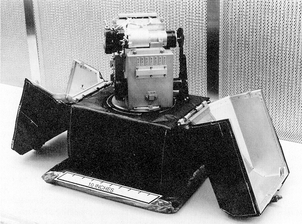
Figure 1. Photograph of the Energetic Particles Detector (EPD) with the dust covers open and with no thermal blanket on the detector heads and time-of-flight electronics box.
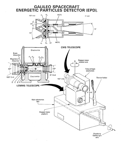
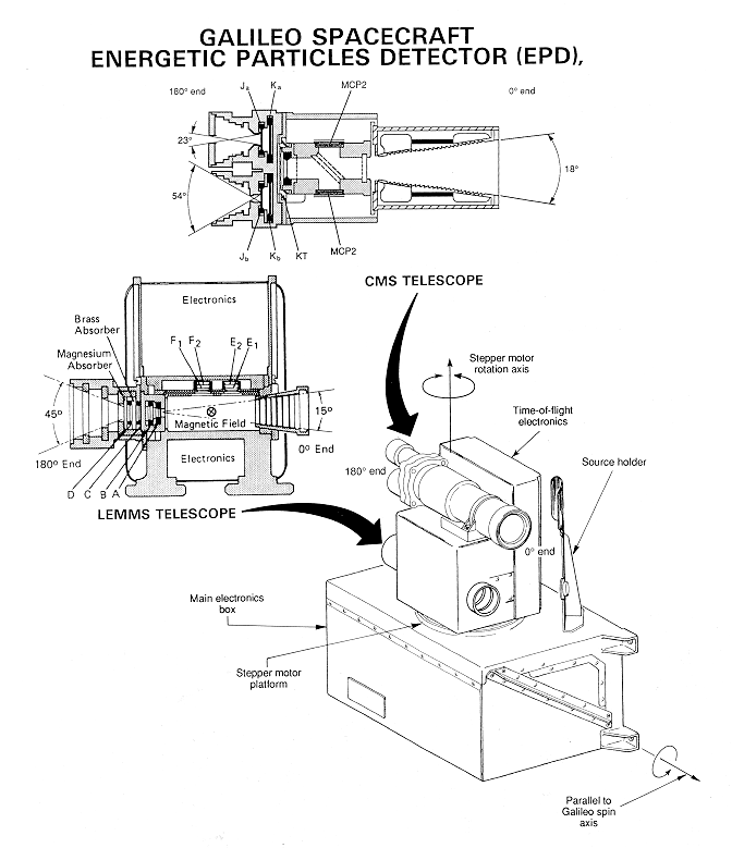
Figure 2. Schematic showing the EPD telescope heads, the overall EPD configuration, the EPD stepper motor rotation axis, and the Galileo spin axis direction.
For a larger view: Fig. 2 (672x779, 71 k)
The general characteristics of the EPD are listed in Table 2. A picture of EPD is shown in Figure 1 and a schematic representation of the instrument is shown in Figure 2. The two bi-directional solid-state detector telescopes are the Low Energy Magnetospheric Measurement System (LEMMS) and the Composition Measurement System (CMS). These detector heads are mounted on a platform and rotated as shown in Figure 2 by a stepper motor contained in the main electronics box. Figure 3 shows the stepper motor positions as seen looking down on the top of the EPD along the motor rotation axis. The combination of the satellite spin and the stepper motor rotation (nominally stepping to the next position after each spacecraft spin) provides 4 pi steradian coverage of the unit sphere. The 0° ends of the two telescopes (see Figure 3) have a clear field of view over the unit sphere and also can be positioned behind a foreground shield/source holder for background measurements and in-flight calibrations. The 180° ends experience obscuration effects in motor positions 4, 5, and 6 caused by the magnetometer boom and foreground shield.
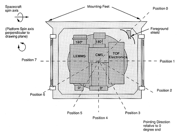
Figure 3. View looking down on EPD along stepper motor rotation axis showing EPD viewing positions. Galileo spin axis direction is parallel to plane of figure and from right to left. Up to 60 samples per spin for the nominal spin period of 20 seconds are obtained, giving good angular resolution over the full 4 pi steradian of the unit sphere.
The 0° end of the LEMMS unit uses magnetic deflection to separate electrons from ions and provides, from detectors A and B, total-ion energy spectra above ~ 20 keV and from detectors E1, E2 and Fl, F2, electron spectra above ~ 15 keV. The 180° end of LEMMS uses absorbers in combination with detectors C and D to provide measurements of ions > 16 MeV and electrons > 2 MeV.
The 0° end of the CMS telescope employs a time-of-flight (TOF) versus total energy technique to measure elemental energy spectra above 10 keV/nucleon for helium through iron . A sweeping magnet in the entrance collimator prevents electrons with energies < 265 keV from entering the system. TOF start and stop pulses are generated as the incoming ions pass respectively through a thin entrance foil and impinge on the detector KT. Electrons released from the foil and the detector are accelerated and deflected through a series of grids and are detected by the microchannel plates, MCPl and MCP2. The time difference between the start pulse, MCP1, and the stop pulse, MCP2, is then obtained, along with the ion total energy from KT. Knowing the ion total energy and its travel time through the system (which gives its velocity), the ion mass is determined.
The 180° end of the CMS telescope measures the ion energy loss, DELTA E, as the ions pass through detectors Ja and Jb and the ion residual energy E = Etotal - DELTA E,, as they impact detectors Ka and Kb. The resulting DELTA E and E measurement provides a measure of ion composition for energies 200 keV/nucleon.
The planned normal mode of EPD operation is to have both telescopes powered and to step the stepper platform once each satellite spin. This will yield a 4 pi scan of the unit sphere approximately every 140 seconds. Many other scanning modes are available and will be used for special circumstances. For example, during satellite encounters the EPD will be configured to scan particular directions such as the expected direction of the magnetic flux tube, the direction of the Galilean satellite wakes as they travel through the Jovian magnetosphere, and the direction of E x B drift paths.
A more detailed description of the EPD hardware follows. The primary elements of this system are the LEMMS/CMS detector heads with their analog electronics, the motorized scanning system, the digital and support electronics, and the data system. Figure 4 shows a functional block diagram of the EPD to be referred to when reading the following sections.
The LEMMS telescopes are designed to measure low to medium energy ion and electron fluxes with wide dynamic range and high angular (< 20°.) and temporal (1/3 to 4/3 seconds) resolution. As stated previously, a full 4 pi coverage of the unit sphere is obtained by the use of a stepping platform in conjunction with satellite spin.
The LEMMS detector head (shown in Figure 5) is a double-ended telescope containing eight heavily shielded silicon solid state surface barrier totally depleted detectors providing measurements of electrons from 15 keV to > 11 MeV, and ions from 22 keV to - 55 MeV, in 32 rate channels that are summarized in Figure 6 and Table 3 The LEMMS design uses a baffled collimator and shaped-field magnetic deflection to provide clean separation between ions and electrons in Detectors A, E, and F (0° end in Figure 5), and extends measurements to much higher energies via Detectors C and D in the oppositely-directed double-absorber-detector telescope stack on the 180 ° end. The functions of the different LEMMS detector and mechanical subsystems are discussed in the following sections.
3.1. LOW ENERGY ION (Z °= 1) TELESCOPE: DETECTORS A, B
This is the primary set of detectors for measuring low energy ions (- 22 keV) in the Jovian magnetosphere. Particles entering through the 15° full angle collimator of LEMMS pass through a series of eleven baffle plates that define seven hexagonal entrance aperture channels converging toward detector A (Figure 5). This geometry provides a relatively wide aperture with the narrowly-defined total acceptance angle necessary for the focused deflection of electrons in the shaped magnetic field beyond the aperture plates. Electrons < 1 MeV are deflected away from detector A, and focused onto detectors E and F for analysis. Ions pass through the field region with relatively little deflection and impact on detector A, a 25 mm2, 102 µ thick surface barrier detector mounted with the aluminum contact out to minimize radiation damage. Detector B is 35 mm2 in area and 984 µ thick. The total geometry factor for detector A and the A/B pair is 0.006 cm2 sr. Ions (Z >= 1) impacting A are measured in 8 differential rate channels covering the energy range from 22 keV to 3.5 MeV. Additional high energy Z = 1, Z >= 2, and electron channels are defined using coincidence logic between A and B. In addition to these fast discriminator and accumulator-based rate channels the output of detector A is digitized to provide a 46-channel energy spectrum (22 - 290 keV) approximately once every 4 2/3 seconds. Background contamination at Jupiter is minimized by coincidence/anticoincidence conditions between detectors, and by surrounding platinum-iridium shielding 62; 12 gm/cm2 thick. The lowest energy discriminator on the output of A can be raised to 27 keV by command in the event of a system noise increase.
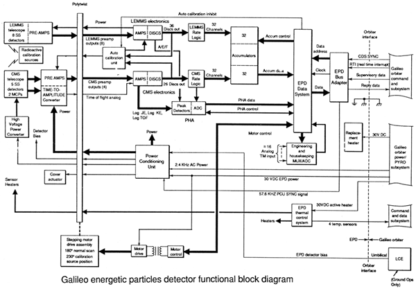
Figure 4. EPD functional block diagram.
For a larger view: Fig. 4 (1126 x783, 175k)
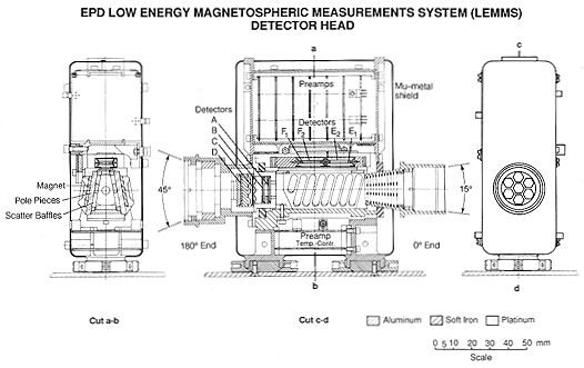
Figure 5. Detail of the EPD LEMMS detector head.
For a larger view: Fig. 5 (1145 x 653, 105k)
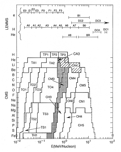
Figure 6. Graphical summary of EPD energy and species rate channel coverage. Additional high energy resolution and detailed species identification are obtained from pulse height analysis data gathered simultaneously with the rate channel data shown.
3.2 LOW ENERGY ELECTRONS: DETECTORS E1, E2; F1, F2
Figure 5 shows the collimator and magnetic deflection region of the low energy end of the LEMMS telescope. Co-Sm permanent magnets generate an inhomogeneous magnetic field between inclined pole pieces with a maximum center line strength of about 650 gauss. Entering electrons are focused onto detectors E1 (> 15 to 200 keV) and F1 (~ 100 to > 1000 keV), which provide the low energy electron measurements for the EPD experiment. Both detectors are rectangular, 45 mm2 surface barrier silicon detectors. E1 is 303 µ thick, F1 is 1097 µ thick, and both are backed by 300 µ thick detectors (E2, F2) of equal area operated in anticoincidence to actively reduce any background penetrating the surrounding shielding of 2 6 gm/cm2 of platinum-iridium alloy. No electron < 1 MeV can directly reach detector A, and no non-deflected particle can directly reach detectors E1, F1. The inside of the deflection volume (inside of the yoke, pole pieces and magnets) is lined with aluminum baffles to minimize scattering.
-------------------------------------------------------------------------------
Channel  Species        Energy Range             Readout Interval**
Name                    (MeV)                    (in 1/3 s)
-------------------------------------------------------------------------------
A0       Z >= 1         0.022 -   0.042               1
A1      Z >= 1         0.042 -   0.065               1
A2       Z >= 1         0.065 -   0.120               2
A3       Z >= 1         0.120 -   0.280               2
A4       Z >= 1         0.280 -   0.515               2
A5       Z >= 1         0.515 -   0.825               2
A6       Z >= 1         0.825 -   1.68                2
A7       Z >= 1         1.68  -   3.20                2
A8       Z >= 2         3.50  -  12.4                 4
B0       Z >= 1         3.20  -  10.1                 4
B1       electrons     ~1.5   -  10.5                 4
B2       Z = 2          6.0   - 100.                  4
DCO      Z >= 1        14.5   -  33.5                 4
DCl      Z >= 1        51.    -  59.                  4
DC2      electrons            >~  2.                  4
DC3      electrons            >~ 11.                  4
E0       electrons      0.015 -   0.029               1
E1       electrons      0.029 -   0.042               1
E2       electrons      0.042 -   0.055               2
E3       electrons      0.055 -   0.093               2
F0*      electrons      0.093 -   0.188               2
F1       electrons      0.174 -   0.304               2
F2       electrons      0.304 -   0.527               2
F3       electrons      0.527 -   0.884               2
AS       singles        All counts in detector        8
BS       singles        All counts in detector        4
CS       singles        All counts in detector        4
DS       singles        All counts in detector        4
EB1      background     Sidewise penetrators          4
EB2      background     E1E2 coincidences             4
FB1      background     Sidewise penetrators          4
FB2      background     F1 F2 coincidences            4
-------------------------------------------------------------------------------

* Channel F0 is the sum of ~ 100-200 keV events seen in detectors El and F1.

** At nominal 3 RPM:    1/3 sec = 60 Readouts/spin, 6 deg. "sectors"
                        2/3 sec = 30 Readouts/spin, 12 deg. "sectors"
                        4/3 sec = 15 Readouts/spin, 24 deg. "sectors"

LEMMS PHA is accumulated for 2/3 sec every 4.66 sec. There are 46 linear
channels and one high energy channel.

Sequence is:  11 spectra from Det. A (20 keV - 290 keV at 6.4 keV/ch)
               1 spectra from Det. E1 (15 keV - 190 keV at 4.5 keV/ch)
               1 spectra from Det. F1 (80 keV - 890 keV at 20.1 keV/ch)

This sequence is 60-2/3 sec long, and repeats.
-------------------------------------------------------------------------------
The efficiencies of the electron detectors have been measured as a function of energy and input direction relative to the collimator central axis. Sample results from detector E are shown in Figure 7(a) and 7(b) at electron energies of 40 keV and 80 keV. At these energies detector F efficiencies effectively are zero. The effect of the honeycomb aperture (Figure 5) clearly is seen.
Also the geometric factor of the collimator and magnetic optics system has been analyzed by extensive computer modeling (Wu and Armstrong, 1988). The energy-dependent aperture-integrated geometry factors for detectors E1 and F1 are shown in Figure 7(c) AND 7(d). The detector efficiencies and geometric factor calculations, as represented by Figure 7, provide a complete determination of the response of the LEMMS electron channels to electrons entering the aperture. The outputs of detectors E and F1 are registered in eight differential accumulator-based fast rate channels and are separately pulse-height analyzed to provide 46 channel energy spectra for each detector (Table 3).
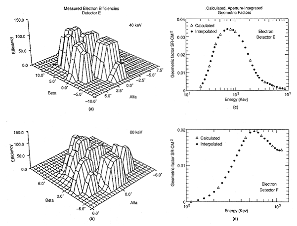
Figure 7. Response of the EPD LEMMS low energy electron detectors. The geometric factor, as calculated from a detailed simulation of the LEMMS head, is shown as a function of energy.
For a larger view: Fig. 7 (998 x 756, 284K)
3.3. HIGH ENERGY ELECTRONS AND IONS: DETECTORS C, D
The C, D detector telescope is used to extend the energy range of the LEMMS electron and ion measurements to higher energies. Both detectors are ~ 100 mm2, ~ 500 µ thick devices separated by 0.48 cm. The detectors are shielded from the side by > 7.24 gm/cm2 of platinum and the rear-facing collimator provides a directional field of view of ~ 45°, resulting in a geometric factor of ~ 0.5 cm2 sr. In the look direction detector D is shielded by a magnesium disk 2 mm thick (0.36 gm/cm2), and between D and C there is an additional absorber of 3.2 mm of brass (2.8 gm/cm2). The detectors each have two discriminator thresholds and operate both in coincidence/anticoincidence and in singles modes that, combined with the magnesium and brass absorbers, define directional thresholds of > 2 and > 11 MeV for electrons in D and C, respectively, and ion (proton) thresholds of 14.5 and 51 MeV (Table 3).
As shown in Figure 5, all of the LEMMS preamplifiers are packaged in close proximity to their detectors to minimize noise, and all of LEMMS except the mounting feet and collimators is enclosed in a µ-metal shell to reduce magnetic field leakage. All LEMMS detector energy signals except for A and E1 have bipolar pulse shaping with a 1 micro-sec full width. Detectors A and E1 have unipolar Gaussian shaping (0.9 µs full width) and baseline restoration to achieve the lowest possible thresholds for measuring low energy ions and electrons.
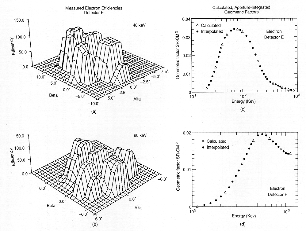
3.4. LEMMS ANALOG ELECTRONICS
Figure 8 shows the block diagram for the LEMMS analog electronics. The unbuffered, preamp tail-pulse output signals are sent down the polytwist wiring harness to three LEMMS analog boards, where the signals are amplified and shaped. All signal processing in the LEMMS channels is done in the linear domain. Comparator-like discriminator circuits assigned to each of the eight channels fire when pre- defined threshold levels are exceeded.
Figure 8. Block diagram of LEMMS analog electronics.
The resulting discriminator outputs are sent to the rate logic electronics, where combinatorial logic is used to define 32 rate channels (event bins). Logic definitions for these channels include requirements for coincidence of some discriminators and anti-coincidence for others; this is used to define desired events. Those events which fall into the rate channels (by having the correct combination of discriminator levels) are counted in custom APL-designed high rate 24-bit accumulators hybrids. The rate data is periodically read into the telemetry stream by the data system. Each channel preamplifier and amplifier electronics can be powered ON/OFF by command.
LEMMS data also are processed through a pulse height analyzer (PHA) that produces 13 46-channel energy spectra per major frame (13 x 4 2/3 seconds). The detector outputs analyzed are selected via command from detectors A, E1, and F1 with the normal selection being 11 spectra from detector A and one each from detectors E1 and F1.
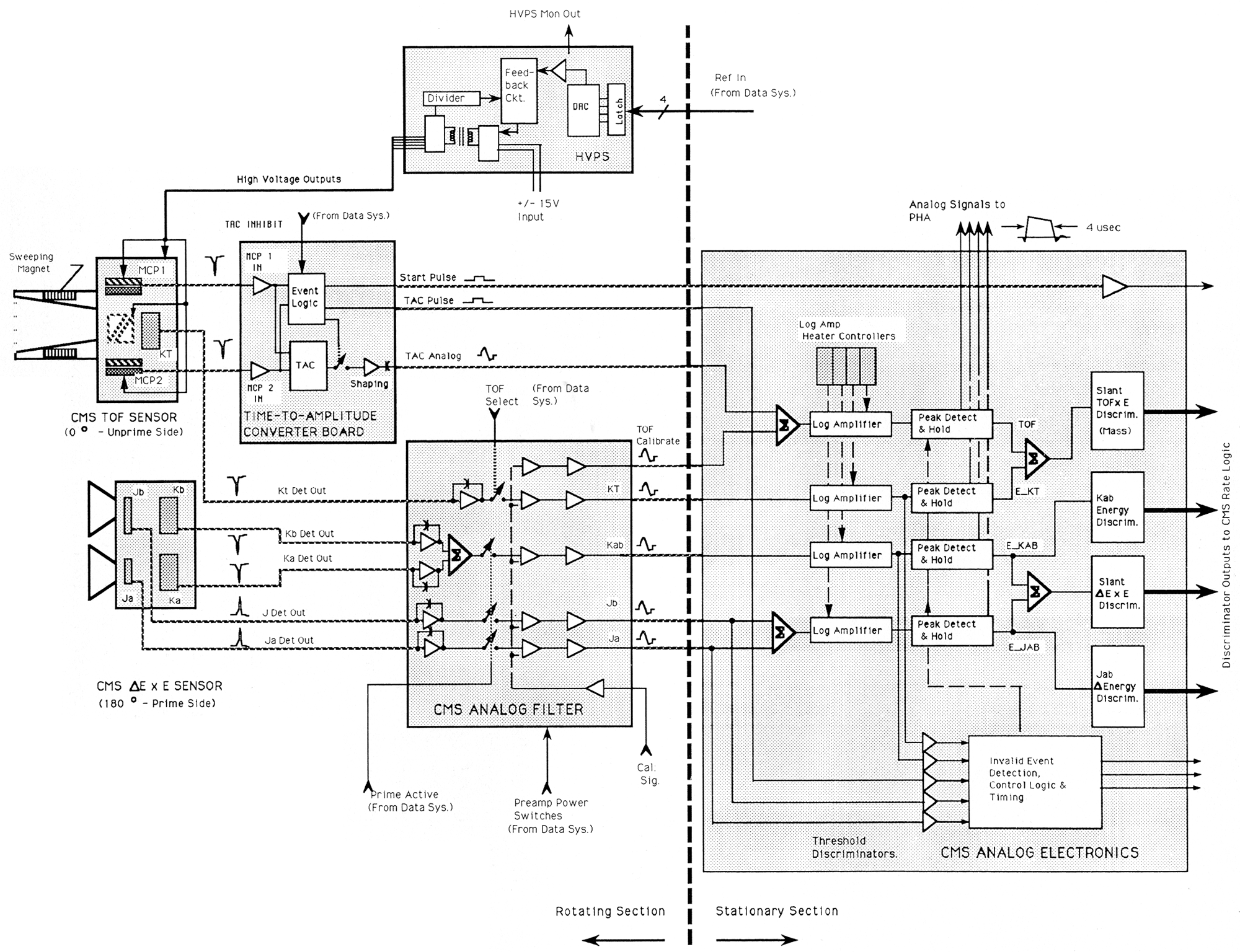
The CMS is designed to measure the composition of ions in the Jovian environment from energies of - 10 KeV/nucleon to > 10 MeV/nucleon. This system contains two types of energetic particle telescopes, shown schematically in Figure 9. A small Time-of-Flight (TOF) telescope looks in the 0°. direction while a pair of DELTA E x E solid state detector telescopes (JK detectors) covering higher energies are oriented in the 180° direction. The location of CMS on EPD is shown in Figure 2, and energy coverage for the combined system is summarized in Figure 6 and Table 4. The CMS subsystems are discussed below.
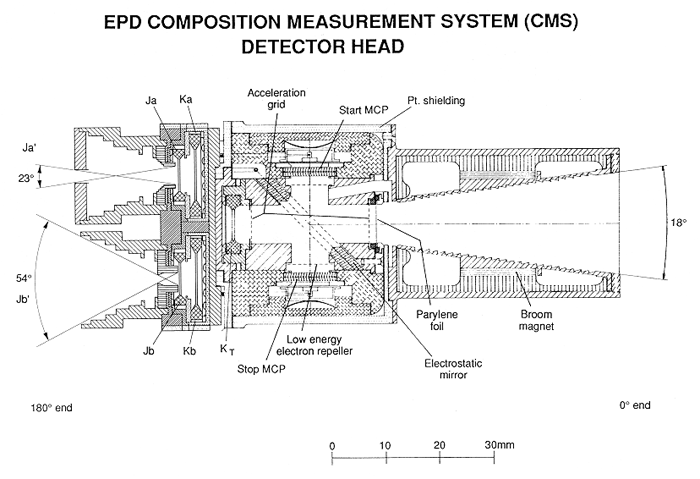
Figure 9. Detail of EPD CMS detector head.
4.1. CMS TIME-OF-FLIGHT (TOF) TELESCOPES
The TOF portion of CMS shown in Figure 9 is a replacement of the original EPD TOF telescope built for launch in early 1986. JPL, NASA, and the Bundesministerium fur Forschung und Technologie allowed us the opportunity to take advantage of new technology in order to lower our energy threshold for composition measurements by at least a factor of ten. This technology was the basis of a new generation of TOF telescopes developed for and/or successfully flown on AMPTE/CCE, VIKING, GIOTTO, and Ulysses (Studemann and Wilken, 1982; Gloeckler et al., 1983; 1985; Wilken and Studemann, 1984; McEntire et al., 1985; Studemann et al., 1987; Wilken et al., 1987). The new TOF telescope, its high voltage power supply, the new TOF circuitry, and the major modifications to the electronics subsystem were designed, built, tested, and integrated into the EPD in 1987 and 1988. All instrument and spacecraft tests and calibrations were successful and were indicative of an instrument response that exceeded expectations.
-------------------------------------------------------------------------------
Channel  Species      Energy Range     Channel   Species        Energy Range
Name                  (MeV/Nucleon)    Name                     (MeV/Nucleon)

TOF X E                                Delta E x E

TP1                   0.08 - 0.22
TP2      Protons      0.22 - 0.54
TP2                   0.54 - 1.25

TA1      Alphas       0.027 - 0.155    CA1                      0.19 -  0.49
TA2                   0.155 - 1.00     CA3       Alphas         0.49 -  0.68
                                       CA4                      0.68 -  1.4
TO1                   0.012 - 0.026
TO2      Medium       0.026 - 0.051    CM1       Medium         0.16 -  0.55
TO3      Nuclei (O)   0.051 - 0.112    CM3       Nuclei (O)     0.55 -  1.1
TO4                   0.112 - 0.562    CM4                      1.1  -  2.9
                                       CM5                      2.9  - 10.7

TS1      Intermediate 0.16  - 0.030    CN0       Intermediate   1.0  -  2.2
TS2      Nuclei (S)   0.030 - 0.062    CN1       Nuclei (Na)    2.2  - 11.7
TS3                   0.062 - 0.31

TH1*     Heavy                         CH1       Heavy          0.22 -  0.33
         Nuclei (Fe)  0.02  -   0.20   CH3       Nuclei (Fe)    0.33 -  0.67
                                       CH4                      0.67 -   .3
                                       CH5*                     1.3  - 15.0

TACS*    Singles                       JaS*      Singles
STARTS*  Rates                         JbS*      Rates
KtS*                                   KS*
-------------------------------------------------------------------------------
* These channels are read out every 8/3 seconds. All other CMS channels are
  read out every 4/3 seconds.
The CMS TOF telescope, as shown in Figure 9, consists of a collimator containing a sweeping magnet followed by a thin-foil solid state detector telescope with an effective geometric factor of 0.007 cm2 sr. The thin (36 11gm/cm2 total thickness) parylene front foil is doubly aluminized to reject both light and scattered Ly-alpha background. It is mounted on a 90% transparency stainless steel grid that is followed by a 3.77 cm time-of-flight path to the rear solid state detector KT (50 mm2, 12.6 µ thick). Secondary electrons are emitted from each surface when an incident ion traverses the front foil and impacts KT. The electrons from the inner surface of the foil and the aluminum front surface of KT are electrostatically accelerated and reflected through 90° onto microchannel plates (MCP's) that provide (respectively) "start" and "stop" fast timing pulses to measure the ion time-of-flight between the front foil and KT. The ion energy is measured in Kcts KT and the incident ion mass is determined by the measured velocity and energy (with corrections applied for the K pulse height defect and dead layer). The microchannel plates are 1.4 cm diameter, 12 µ pore size, 80/1 ratio, 200 mega-OMEGA plates operated in chevron configuration at a gain of ~ 5X10⁶. Because these devices are sensitive to contamination, the EPD telescopes were purged with N2 up until launch. The MCP's and electrostatic optics are powered by a single HV power supply, adjustable over the operational range in 14 steps (up to a maximum of 4.6 KV) to maintain constant MCP gain over the mission life. Predicted track locations of several elements in the TOF versus energy space measured by the telescope are shown as dashed lines in Figure 10. The resolution limit of the sensor is set primarily by two factors; at higher Z and lower energies it is set by pulse-height-defect spread in the energy measured in KT, while at high energies the limiting factor is the 0.6 nsec (FWHM) timing resolution of the electron optics and electronics. For example the telescope can resolve H1, H2, He3, He4, C, O, and the major Jovian species and species groups with a mass resolution that is a function of both mass and energy. Vertical energy discriminators and slanted mass discriminators (defined on the logarithmic sum of the energy and TOF pulse height) are defined (solid lines) to separate TOF-E space into 13 composition channels covering the species or species groups listed in Table 4. These accumulator-based composition rate channels (and associated singles channels) provide good flux and angular information on abundant species with (in some modes) 100 percent duty cycle but with moderate energy and species resolution. A much more precise spectral and elemental resolution is obtained from 256-channel pulse-height analysis (PHA) of the energy and TOF signals for individual events. An average of ~ 4 of these fully-analyzed events are transmitted per second (selected by a 4-level adaptive priority system used to obtain balanced coverage over species and energy and shared between the CMS TOF and DELTA E x E telescopes). These PHA data, normalized by the rate-channel count rates, allows detailed fluxes and spectra to be obtained for each element measured. Figure 10 contains PHA data from sample calibration runs at the Goddard Space Flight Center and University of Rutgers accelerators where the telescope was calibrated with beams of H, He, C, O, Ne, Na, S, Ar, Fe, and Kr from energies below 100 keV to over 10 MeV. The TOF head is resistant to electron pile-up and over most of the orbit will be insensitive to penetrating background due to shielding and coincidence requirements. A valid TOF head event requires a triple coincidence (a start MCP event followed within 60 ns by a stop MCP event, and a coincident KT energy pulse). The sweeping magnet prevent electrons ' 185 KeV from reaching the front foil, and electrons ' 265 KeV from directly reaching the rear detector. This detector, KT, has a lower threshold of 66 KeV (which can be increased to 122 KeV by command) and due to its 12.6 µ thickness is insensitive to energetic electrons in its field of view. All active components are shielded by a minimum of 3.8 gm/cm-2 of platinum.
4.2. CMS DELTA E x E TELESCOPES
The CMS DELTA E x E telescopes are designed to extend the CMS ion composition (Z >= 2) measurements to significantly higher energies than are attained by the TOF telescope. These rear (180° direction) facing telescopes are shown in cross section in Figure 9. Each consists of a thin front solid state detector (Ja,b) followed by a thick rear detector (Ka,b). Ja is 44 mm2, 5.5 µ thick, Jb is 23 mm2, 5.6 µ thick, and Ka,b are each ~ 200 mm2, 185 µ thick. Apertures for each telescope are defined by an aluminum collimator and a field stop immediately in front of each J detector. This yields geometry factors of 0.008 cm2 sr for Ja and 0.025 cm2 sr for Jb. The two telescopes provide redundancy and the geometry factors are chosen to minimize radiation damage accumulated over the Galileo mission.

Figure 10. TOF versus Energy observed in detector KT. Discriminator levels defining the indicated TOF rate channels (solid lines), predicted TOF vs. E curves (dashed lines), and data from accelerator calibrations (points) are shown.
In each telescope the J and K detectors are primarily operated in coincidence, with dE/dx measured in J and total residual energy measured in K. The DELTA E X E energy space measured is shown in Figure 11, with dashed lines showing predicted DELTA EJ X EK tracks for a number of elements over the telescope range of energies. Energy discriminators on J (horizontal lines) and K (vertical lines), and two discriminators defined on the logarithmic sum of the J and K energy measurements (slanted lines) define 10 discrete composition channels covering the species shown in Figure 6 and summarized in Table 4. The three single parameter (JK) channels CA1, CM1, and CH1 (shown below the lowest K discriminator in Figure 11 but not shown in Figure 6) extend measurements (Z > 2, 3, 12, respectively) to lower energies in order to increase overlap with the TOF telescope. The dashed line on the right in Figure 6 indicates the energy of penetration of the K detectors. The actual sensitivity of the telescope extends to higher energies. As with the TOF telescope, the accumulator-based DELTA E x E rate channels can provide coverage with essentially 100% duty cycle and very wide dynamic range. Detailed spectral and species resolution is derived from PHA events transmitted at ~ 4 events/second. Figure 11 contains sample PHA data taken during calibration runs at the Rutgers Tandem Van de Graff accelerator where the DELTA E x E telescopes were calibrated with beams of He, Li, C, O, F, Na, Si, S, and Fe over a wide range of energies. As can be seen from the figure, elemental resolution is possible (depending on relative abundance) through sodium and all major Jovian species and species groups will be distinguished.

Figure 11. Energy loss in detector J, (DELTA E), versus energy measured in detector K, (E). Discriminator levels defining the indicated rate channels, predicted DELTA ExE curves, and data from accelerator calibrations are shown.
Each of the JK detector pairs is surrounded by >= 2.5 gm/cm2 of platinum and aluminum shielding. Coincidence and anticoincidence requirements on valid events, and discriminator thresholds set well above expected energy depositions for foreground electrons and most penetrating particles, allow the DELTA E x E telescopes to make clean measurements in all but the most intense portions of the Jovian radiation environment.
4.3 CMS ANALOG ELECTRONICS
Figure 12 shows a block diagram of the CMS analog electronics. The velocity measurement is made via the Time-to-Amplitude Conversion (TAC) electronics, which measure ion velocity by converting microchannel plate-produced start and stop charge pulses into a bipolar linear signal whose amplitude is proportional to the time-of-flight of the ions over a known distance. The analog signal shaping times are similar to those used on the other CMS channels.
Unlike the LEMMS processing, the energy and time signals are logarithmically compressed after initial amplification. This enables direct calculation of mass from time and energy data using linear analog circuitry and extends the dynamic range of the channels to three decades. These advantages come at the expense of rate capability; the log amp recovery time can be as great as 40 µs (for the worst case situation of very large energy signals in the K detector), and represents the limiting rate factor in the CMS electronics chain. The TOF telescope requires significant rate corrections at input count rates of >= 150 Kcps. The DELTA E x E electronics can experience pile-down effects at >= 50 Kcps, a value that is energy dependent.
As in LEMMS, discriminator circuits are assigned to each of the analog channels, allowing energy and species categorization to be performed. The 26 discriminator outputs are sent to the rate logic board, where combinatorial logic is used to define 32 rate channels (event bins). The data are accumulated and read into the data system as in LEMMS.
In addition to the rate channel measurements, the instrument is able to perform higher resolution analysis of events using a pulse height analyzer, (PHA). This circuit performs an 8-bit A/D conversion of the relevant energy and time parameters. In LEMMS, this is used to produce a 47-bin single channel energy spectrum for the three low energy ion and electron channels. In CMS a 256 x 256 dual parameter measurement is made of DELTA E x E and Total Energy x Time-of-Flight.
Due to processing and telemetry limitations, only a small fraction of all events are analyzed by the PHA. Approximately 7 LEMMS energy spectra and 230 CMS dual parameter measurements are produced every minute.

Figure 12. Block diagram of CMS analog electronics.
For a larger view: Fig 12. (2000 x 1536, 1028k)
The LEMMS electronics can be modeled as 8 independent, non-paralyzable channels with 1.4 µs dead-times. Events rates up to 600 KHz can be measured in each channel without requiring significant rate corrections. Figure 13 shows the measured true versus apparent count rate response of the LEMMS.

Figure 13. Apparent versus true count rate measured for LEMMS rate channels.
The CMS electronics is more rate restricted, however. The log amplifier recovery time is a function of both the signal level and overall event rate. Performance in each channel, while independent up to and beyond the log amplifiers, is affected by the common event timing logic. As mentioned above, energy piledown occurs in the CMS DELTA E x E energy channels at rates of > 50 Kcps (depending upon event energy distribution). The Time-of-Flight system is less sensitive to these problems and will operate to rates well above 150 Kcps.
Full 4 pi solid angle coverage is provided to the EPD sensors by using a motor subsystem to step the detector assemblies through 228° of rotation (see Figure 3). This stepping, in conjunction with the approximately 3 revolution-per-minute rotation of the spacecraft science boom, provides three dimensional angular resolution of the measured particle distributions, as indicated in Figure 2.
The scanning system is a microprocessor-based positioning system designed to be automatic, self-correcting, and self-protecting. Optional modes provide extensive flexibility, allow adaptation to most single-point failures, and provide for in-flight program modification. A detailed description of the scanning system is given by Fort (1985).
The system is comprised of several components, including control and driver electronics, opto-isolated position sensors, rotating wiring harness, and the motor itself. The heart of the system is a 4-phase 90° stepper motor acting through a 50:1 reduction gear to yield 1.8° rotational steps at the 78,000 gm cm2 load. The motion is translated to the sensor packages via a beryllium copper shaft and platform. All major sensor structures are mounted to the platform.
A special wiring assembly, called a polytwist, carries 116 power, control, and analog signals between the rotating platform and the main electronics assembly through a 2.26 cm shaft. The polytwist was designed and an identical unit successfully tested for a 500,000 cycle lifetime. The motor is powered from the energy stored in a 0.0127 µF capacitor bank. The capacitors are trickle charged when the system is at rest to reduce the peak power demands on the spacecraft. The motor, drive electronics, and capacitor bank are transformer-isolated from the control circuitry, and are powered separately off the spacecraft power bus. A set of five LED/phototransistor pairs provide positioning information to the RCA 1802 microprocessor-based controller hardware. These sensors identify each of the eight regions, or defined positions within the scan range, as well as provide centerline and control feedback information. Figure 3 shows the motor position definitions.
During normal operation, the system steps through 228.6° and back, stopping at 8 positions to allow for the accumulation of science data and the recharging of the capacitor bank. The angle between motor position centerlines is 30.6°, except for position 0 (calibration position), which is 45° from sector 1. In normal mode, the motor position is changed every 20 seconds, although this may be varied by command to better match a non-standard spacecraft spin rate.
The motor controller receives its commands through the normal instrument command interface via the data system electronics. Motor system status is provided in the instrument telemetry via the data system as indicated in Figure 4.
A great deal of flexibility has been incorporated into the motor control hardware and software. Amongst other capabilities, the system may step at various rates, scan between commandable position limits, operate open loop (in case the position information is not available), change recharge rates, or remain at specified locations. The motor may also be single-stepped between defined positions, using the full energy stored in the capacitors for the 1.8° movement.
Autonomous error recovery routines are available to allow graceful degradation of the system should mechanical or electrical problems be encountered. The control software may be modified in flight to handle unforeseen system limitations.
The EPD instrument contains a highly flexible command, control, and telemetry system. The "brains" of the system is a radiation hardened, RCA 1802 microprocessor-based computer with 6 Kbyte mask programmed ROM and 2.25 Kbyte RAM, and 22 8-bit input/output ports. The system is responsible for all instrument control, command decoding, and telemetry processing and formatting. While this system (as well as other parts of the instrument hardware) may not be impressive by today's VLSI standards, at the time it was designed and built, it was state-of-the-art.
The command and telemetry interface with the spacecraft is made over 4 dedicated serial data lines, three going to the instrument and one going to the spacecraft. These data lines connect to high-speed direct memory address control electronics within the instrument. Through this electronics, the spacecraft is able to directly read and write into the contents of the EPD data system memory.
Commands intended for the EPD are thus written to a specific area in RAM, and formatted telemetry packets are likewise read from alternating buffers in RAM. This whole process is transparent to the instrument microprocessor electronics. Special instrument registers count the number of invalid bus transactions. Each instrument on the spacecraft is connected to the spacecraft bus in a similar manner, thus forming a very flexible distributed processing network.
In addition, there is a low voltage power supply which converts the spacecraft 30 volt DC power into 10 isolated output voltages needed in the instrument. The converter, based upon a buck/boost regulator, operates at 57.6 KHz, and contains overcurrent crowbar protection (350 ma), load switching, and dual detector bias output levels. It operates at approximately 78% efficiency under normal load.
The converter also switches power to the instrument's cover release mechanism. The mechanism, based upon a bi-phase wax actuator and nine-watt heater element, successfully released two clamshell covers which protected the CMS and LEMMS detectors from chemical contamination and physical damage. The covers can not be reclosed during the mission.
The instrument may be calibrated in flight in two ways. Alpha particle and electron radioactive calibration sources are mounted on the foreground shield positioned in motor sector 0. These sources can be seen by both the CMS and LEMMS. An electronic pulser circuit also can be used to generate signals for the LEMMS and CMS analog channels. These pulses are injected after the preamplifier electronics, and are intended to verify channel operation and discriminator settings. A sophisticated feedback circuit enables the data system to automatically cycle the pulsers to each discriminator, measuring the 12% and 88% trigger levels in each to measure channel noise.
Instrument status is monitored through the use of an 8-bit analog to digital converter and multiplexer. Five temperatures, nine voltages, and the instrument input current are measured and reported in the telemetry stream once a minute.
Instrument temperatures are regulated via a system of ten autonomous heater circuits; six are proportionally-controlled linear heaters and four are discretely-controlled switching heaters. The combined maximum capability of the heaters is 10.1 watts, although the power use at Jupiter is expected to be 3.9 watts. The temperature setpoint for most of the heaters is -18° to -20° C. To keep the temperature-sensitive CMS log amplifier circuit gain constant under varying thermal conditions, four of the heaters (one for each amplifier) have setpoints of + 20° C.
In addition to the heaters, the instrument is almost completely enclosed in conductively coated thermal blankets, and is mounted to the science boom via thermal isolators. A spacecraft-provided retractable sun- shade will protect the instrument from the sun during the first three years of the mission
The system is able to receive and execute 6 command bytes per second via a 32-byte command buffer. There are 145 different instrument commands, 54 of which are passed through to the motor via a dedicated command interface. The motor control electronics, discussed above, are operated in a slave mode to the data system, receiving commands and sending motor status information upon request. Four of the instrument commands are actually macro commands, putting the electronics into predefined operating modes. The number of received valid and invalid EPD commands is reported in the instrument telemetry.
Telemetry is sent to the ground via the spacecraft at a fixed 912 bit/sec rate. A new telemetry packet is produced every 2/3 seconds by the instrument (see Figure 14). As this packet is being read by the spacecraft, the next packet is formatted in a different location in RAM. The EPD telemetry packet includes information on instrument status via a subcommutated housekeeping channel; the data is reported for each of the 91 channels once every 60 2/3 seconds.

Figure 14. EPD telemetry packet allocation.
Various EPD telemetry modes may be selected by command, including multiplexing of LEMMS and CMS PHA measurements and simultaneous, alternating, or dedicated measurements from the two CMS detector heads. Many of the subsystems, including the motor, PHA, calibrator, and rate logic may be operated in a number of configurations, allowing reallocation of telemetry to specific channels of interest.
One byte of motor status is generated every packet, including operating mode. position error conditions, etc. This information, together with spacecraft generated navigation and spin parameters, will be used on the ground to sort the received event data into 7 motor position-based sets of 64 spin-based sector bins.
The instrument must be able to adapt to unforeseen problems during the mission. Two ways that this is done are via software changes to the data system and an internal alarm monitor. The EPD operating software can be modified in-flight through the use of RAM software patches. This can be used to "patch" around sections of memory that fail, or add new control algorithms whose need was unforeseen when the ROM-based operating system was created.
The instrument's internal alarm monitor checks 4 temperatures, one voltage and one current against defined alarm thresholds approximately once every subcommutation cycle (60 2/3 sec). If the measured value exceeds the limits, an alarm flag is set in the instrument telemetry, and the instrument configures itself in a Power-On-Reset state. The spacecraft, upon receiving the alarm, will turn off the instrument power. The alarm function can be disabled by command for any or all individual thresholds.
The EPD was launched successfully on board the Galileo spacecraft on October 12, 1989. A full instrument check performed in December 1989 showed completely nominal operation. All data received and operations performed to date indicate continuing nominal operation. A more complete set of data will become available during the first Earth encounter period whose closest approach occurs on December 8, 1990.
The successful construction, test, and launch of the EPD has required the continuing efforts of many dedicated professionals since proposal submission in 1976 and receipt of initial funding in late 1977. Space does not permit the recognition of everyone connected with the EPD over this fourteen year time interval. However, with apologies to inadvertent omissions, we wish to thank and acknowledge those many people who had major and/or continuing responsibilities in the EPD effort. The following major contributors, exclusive of the authors of the present paper and those named therein, are listed with the organizational affiliation existing at the time of their association with EPD: J. Crawford, J. Dassoulas, D. Fort, S. Gary, J. Heiss, B. J. Hook, J. Kohl, H. Malcom, R. Moore, T. Mueller, M. Puntz, S. Purwin, N. Rothman, P. Schwartz, R. Thompson, B. Tossman, J. Townsend, Jr., C. Wingate, and H. Wong, all from The Johns Hopkins Applied Physics Laboratory; W. Boeker, W. Klemme, H. Sommer, W. Weiss, and H. Wirbs, from the Max Planck Institute fur Aeronomie; R. Dayhoff, and C. Holmes, from the NOAA Space Environment Laboratory; W. Fawcett, R. Gibbs, G. McSmith, R. Parrish, J. Taylor, and J. Willett, from the Jet Propulsion Laboratory; S. Brown from Goddard Space Flight Center; and J. Burke and R. Martin, contract employees. Thanks to all of you who have helped make the EPD such a successful effort to date. This work was supported by a National Aeronautics and Space Administration contract to The Johns Hopkins Applied Physics Laboratory under the Department of Navy Task IAYX910X; contract N00039-89-C-0001.
References
Fort, D. E.: 1985, JHU/APL Space Systems Report CP087
Gehrels, N. and E. C. Stone: 1983, J. Geophys. Res., 88, 5537.
Gloeckler, G., Geiss, J., Balsiger, H., Fisk, L. A, Gliem, G., Ipavich, F. M., Ogilvie, K. W., Studemann, W., Wilken, B.: 1983, ESA SP-1050, 75.
Gloeckler, G., Ipavich, F. M., Studemann, W, Wilken, B., Hamilton, D. C., Kremser, G., Hovestadt, D., Gliem, F., Lundgren, R. A., Rieck, W., Tums, E.O., Cain, J. C., Masung, L.S., Weiss, W., and Winterhof, P.: 1985, IEEE Trans. Geosci. Remote Sensing, GE-23, 234.
Krimigis, S. M. and Roelof, E. C.: 1983, in Physics of the Jovian Magnetosphere, ed. A. J. Dessler, 106.
Mauk, B. H. and Krimigis, S. M.: 1987, J. Geophys. Res., 92, 9931.
McEntire, R. W., Keath, E. P., Fort, D., Lui, A. T. Y., and Krimigis, S. M.: 1985, IEEE Trans. of Geoscience and Remote Sensing, GE-23, 230.
Stüdemann, W. and Wilken, B.: 1982, Rev. Sci. Instrum., 53.
Stüdemann, W. and Wilken, B., Kremser, G., Korth, A., Fennell, J. F., Blake, B., Koga, R., Hall, D., Bryant, D., Soraas, F., Bronstad, K., Fritz, T. A., Lundin, R., and Gloeckler, G.: 1987, Geophys. Res. Lett., 14, 455.
Wilken, B. and Studemann, W.: 1984, Nuc. Inst. and Methods, 22, 587.
Wilken, B., Weiss, W., Studemann, W., and Hasebe, II.: 1987, J. Phys. E: Sci. Inst. 20.
Wu, Y. and Armstrong, T. P.: 1988, Nuclear Instruments and Methods in Physics Research, A265, 561.