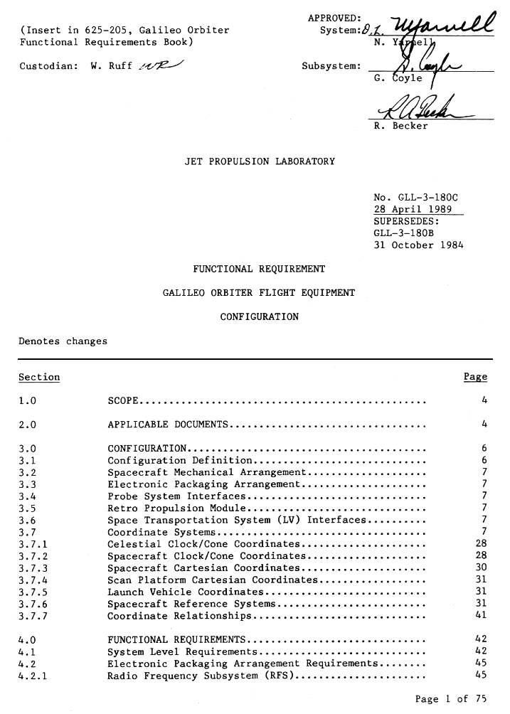
| i) Table of Contents | ||
| page 1, page 2, page3 | ||
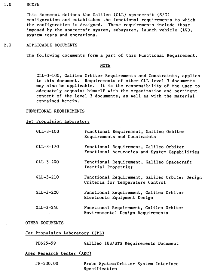
| 1) Applicable documents | ||
| page 4 | Functional Requirements: JPL Other Documents: JPL, ARC |
|
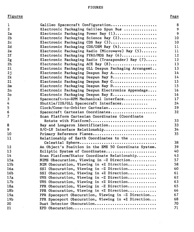
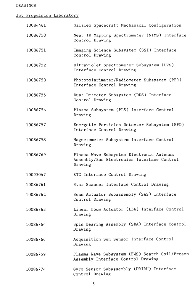
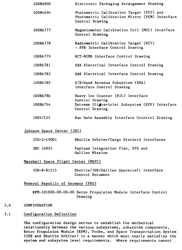
| 2) Technical Drawings | ||
| page 5 | List of Technical Drawings | |
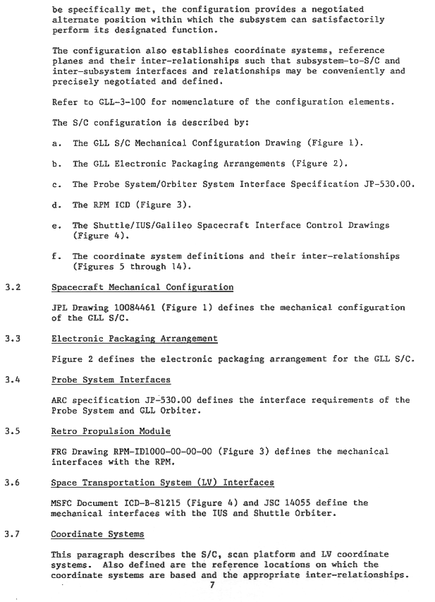
| 3) Configuration | ||
| page 6 | Configuration Definition | |
| page 7 | Config. Def. Cont, Spacecraft Mech. Config., Electronic Packaging, Probe System Interfaces, Retro Propulsion Module, Space Transportation System (LV), Coordinate Systems. | |
| pages 8-27 | Omitted | |
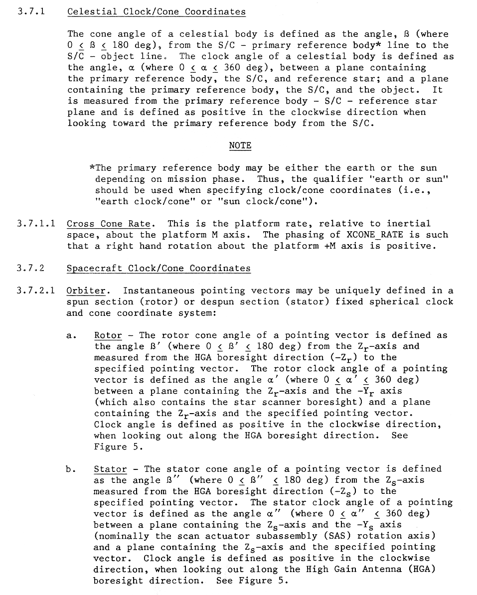
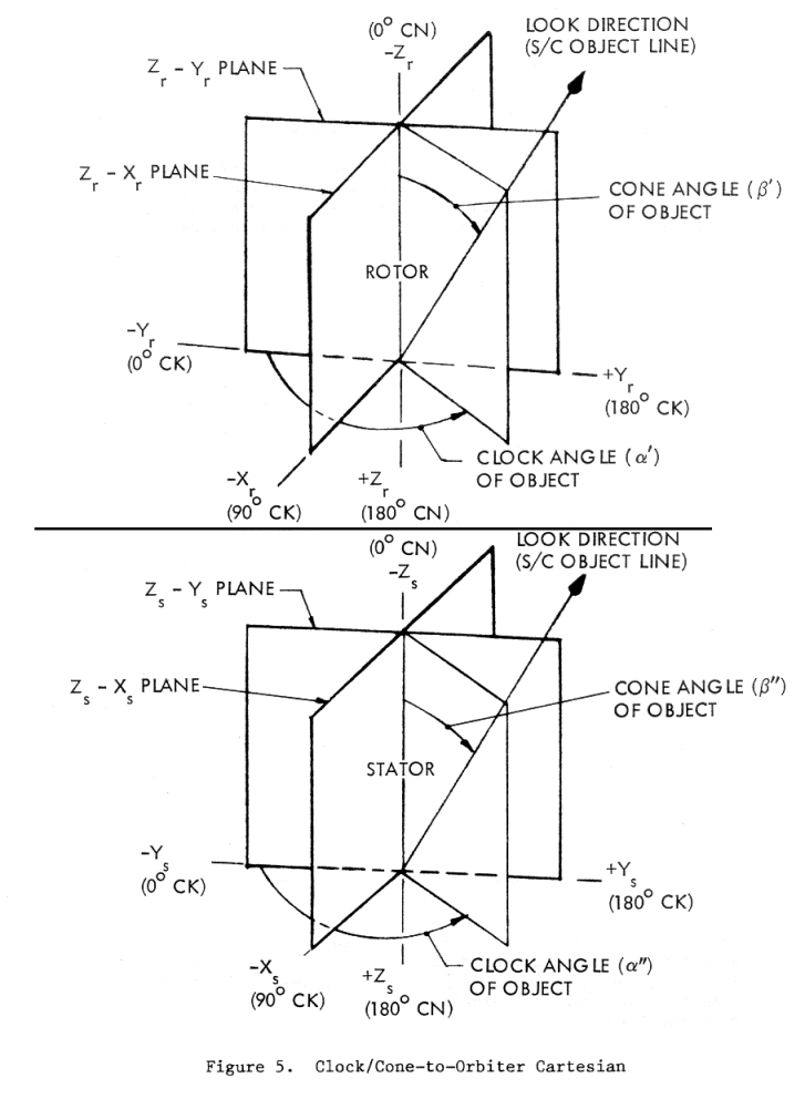
| page 28 | Celestial Clock/Cone Coordinates: Cross Cone
Rate Spacecraft Clock/Cone Coordinates: Orbiter: Rotor, Stator |
|
| page 29 | graphic of rotor and stator clock/cone-to-orbiter Cartesian | |
| page 30 |
Orbiter: Probe Spacecraft Cartesian Coords Orbiter: Rotor, Stator Probe |
|
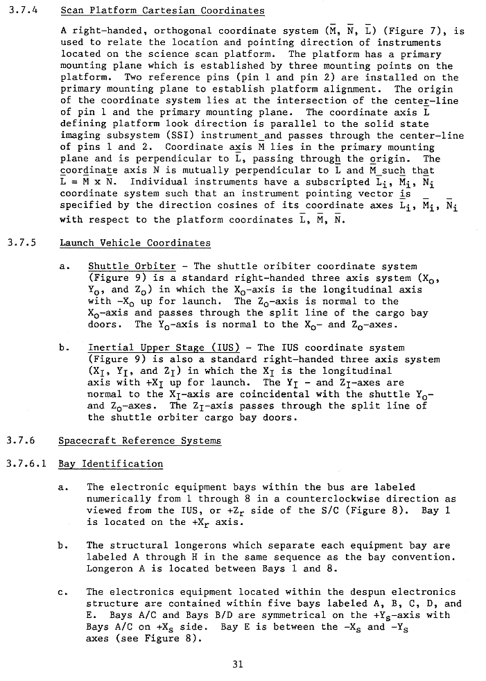
| page 31 | Scan Platform Launch Vehicle Coordinates Shuttle Orbiter IUS Spacecraft Reference Systems Bay Identification |
|
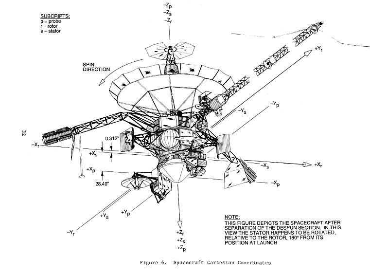
| page 32 | Technical Drawing of Spacecraft after separation of the despun section. | |
| page 33 | Drawing of Bay and Longeron Identification | |
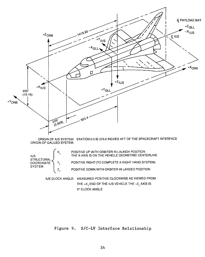
| page 34 | Drawing of the Spacecraft-LV Interface Relationship | |
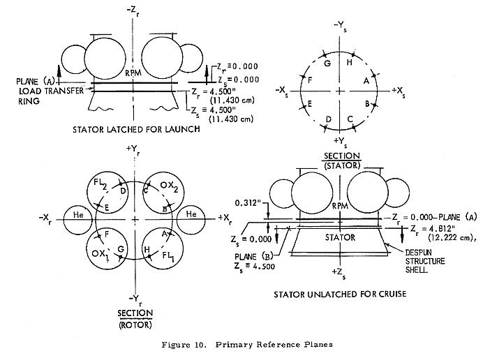
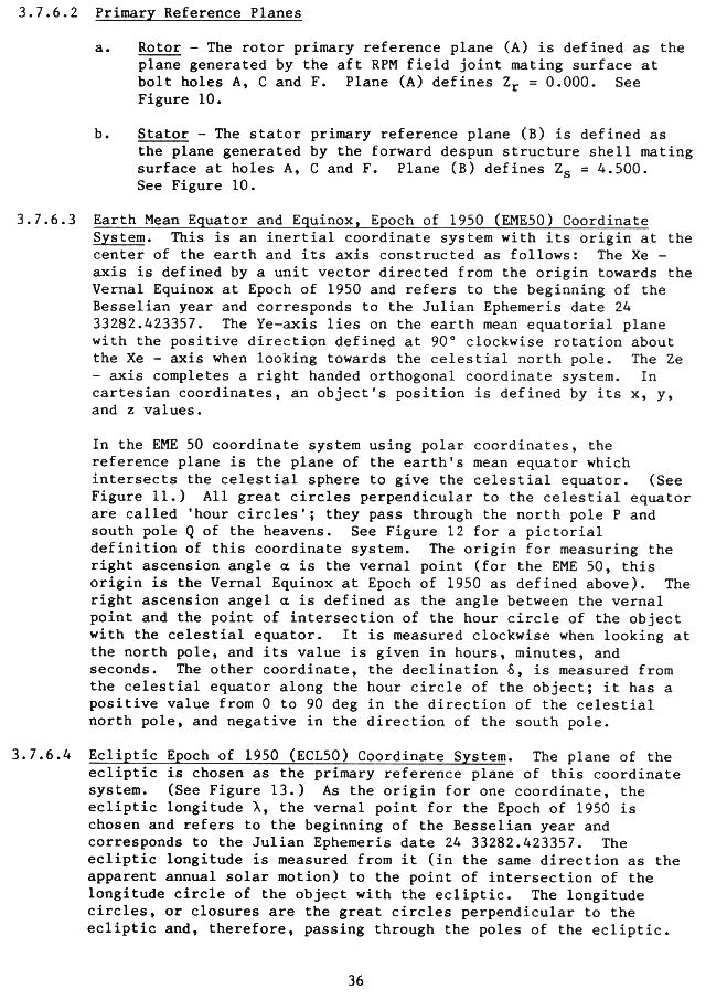
| page 35 | Drawing of the Primary Reference Planes | |
| page 36 |
Primary Reference Planes EME 50 ECL 50 |
|
| page 37 |
ECL 50 Continued S/C Attitude Determination Scan Platform Rotor Twist Angles SBA Encoder Angle Definition SAS Encoder Angle Definition |
|
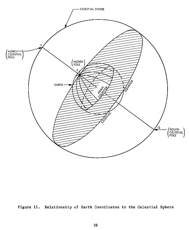
| page 38 | Drawing of the relationship of Earth Coordinates to the Celestial Sphere | |
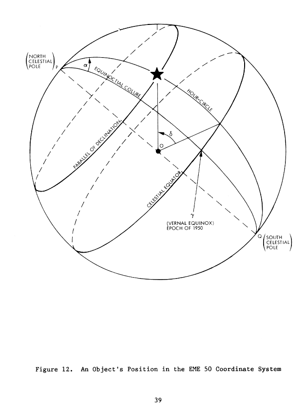
| page 39 | Drawing of an objects position in the EME 50 Coordinate System | |
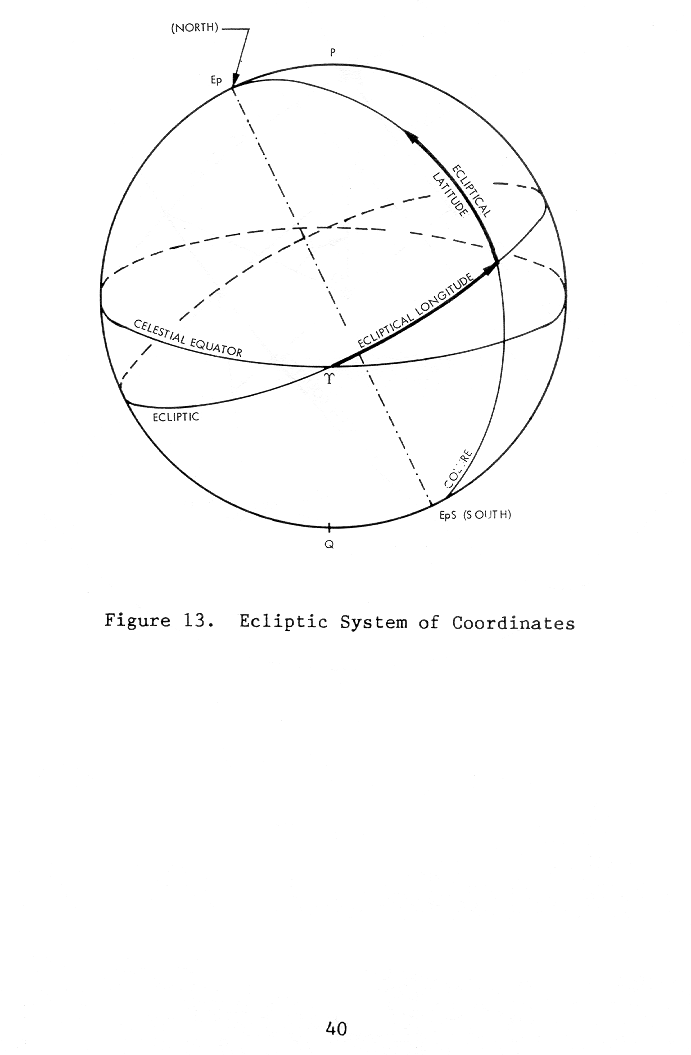
| page 40 | Drawing of the ECL 50 Coordinate System | |
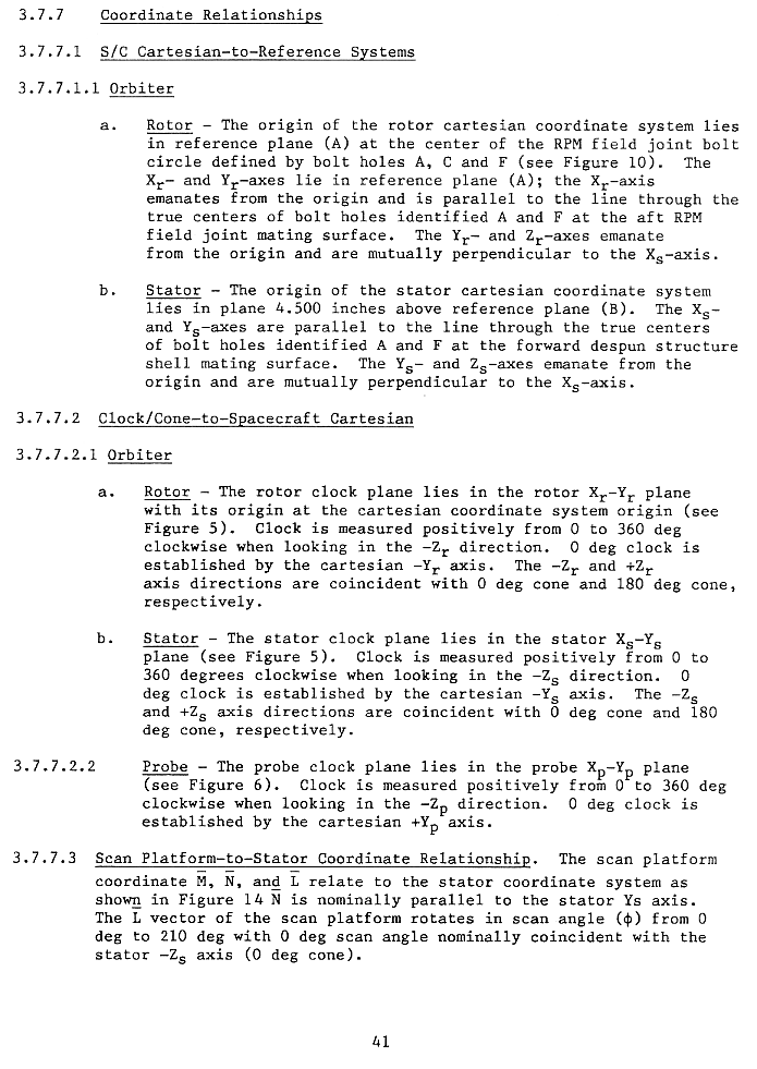
| page 41 | Coordinate Relationships S/C Cartesian to Reference Systems: Orbiter Clock/Cone to Spacecraft Cartesian: Orbiter, Probe Scan Platform to Stator Coordinate Relationship |
|
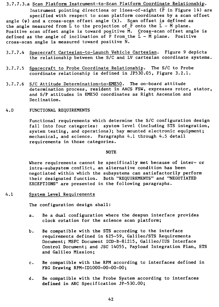
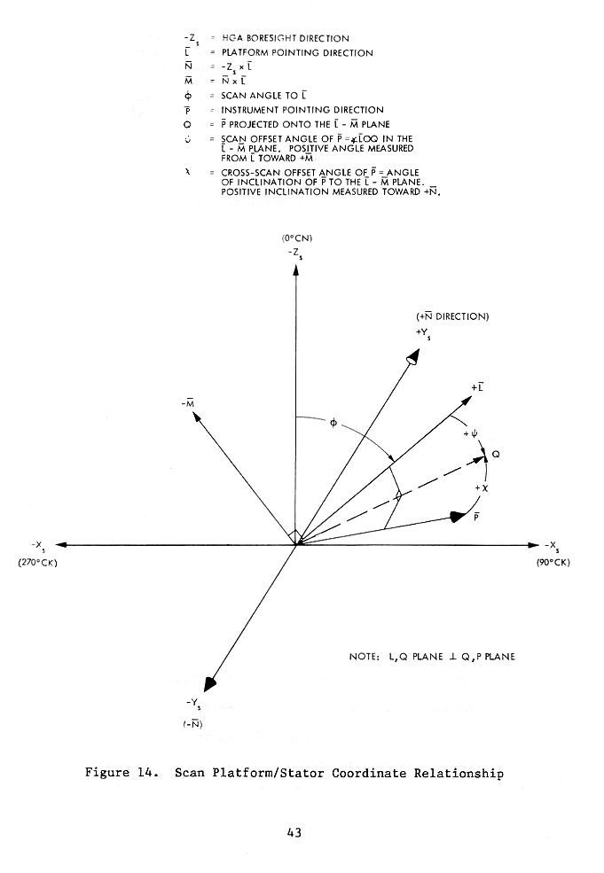
| page 42 |
Scan Platform Inst. to Scan Platform Coord. Relationship Spacecraft Cartesian to Launch Vehicle Cartesian Spacecraft to Probe Coordinate Relationship S/C Attitude Determination to EME50 |
|
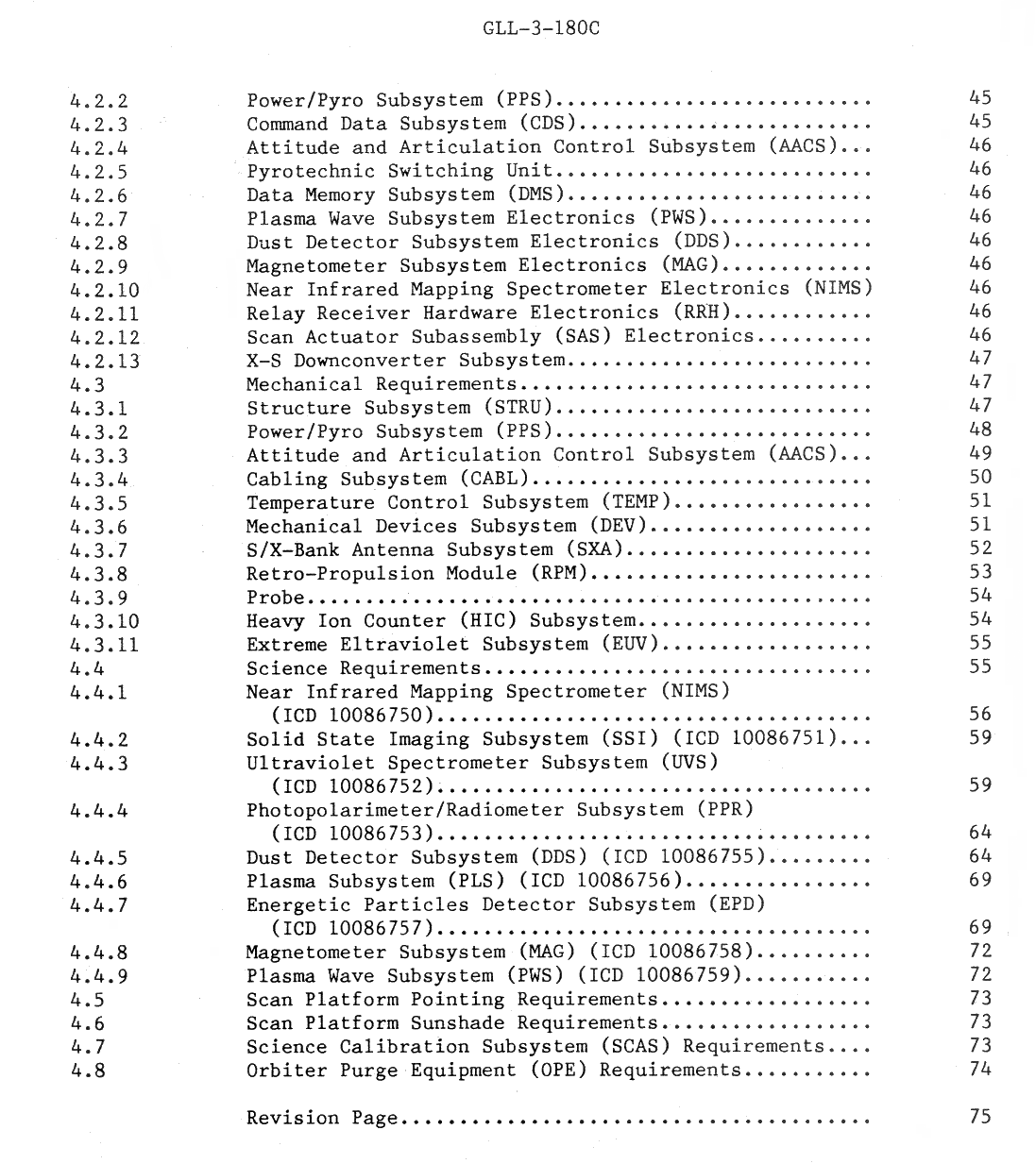
| 4) Functional Requirements | ||
| page 42 | System Level Requirements | |
| Drawing of Scan Platform/Stator Coordinate Relationship | ||
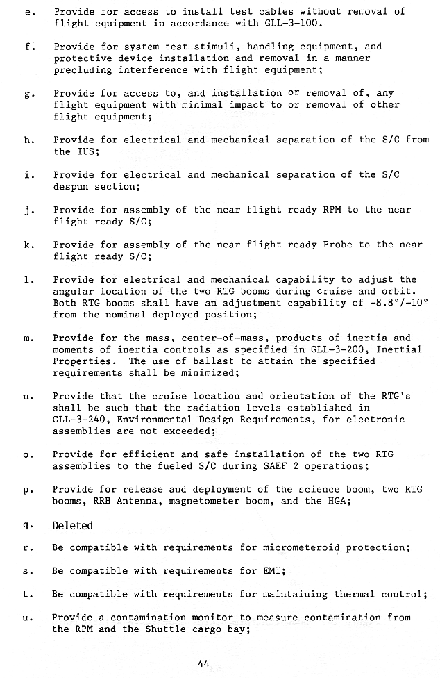
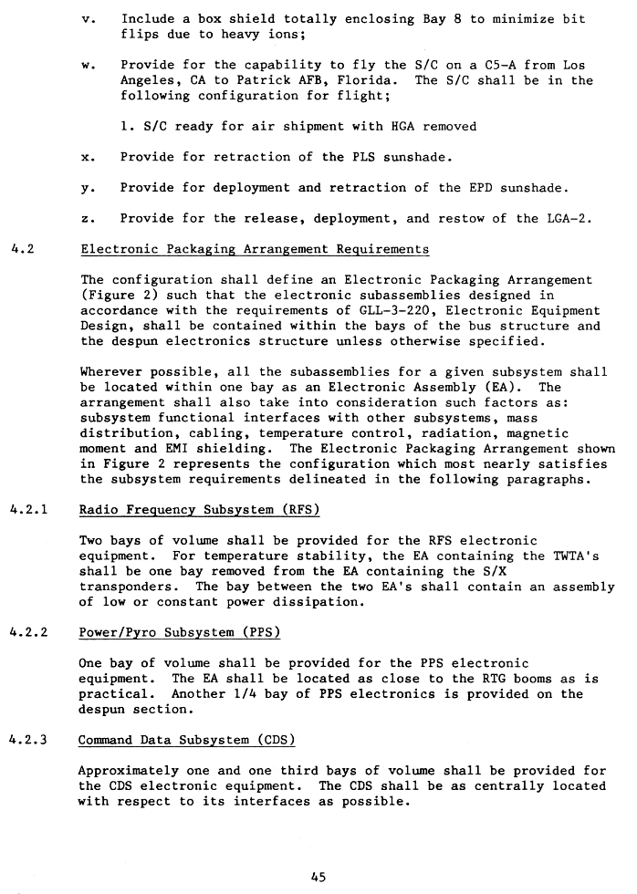
| page 44 | System Level Requirements Continued | |
| page 45 | System Level Requirements Continued Electronic Packaging Arrangement Requirements: RFS, PS, CDS |
|
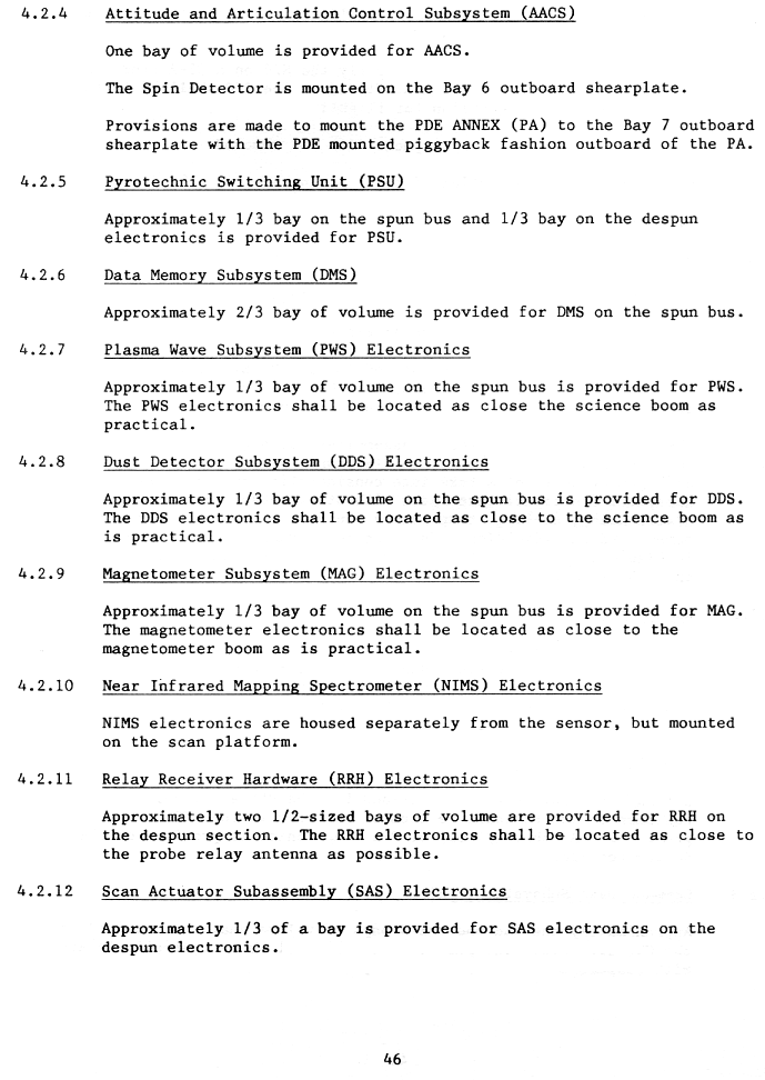
| page 46 | Electronic Packaging Arrangement Cont.: AACS, PSU, DMS, PWS DDS, MAG, NIMS, RRH, SAS | |
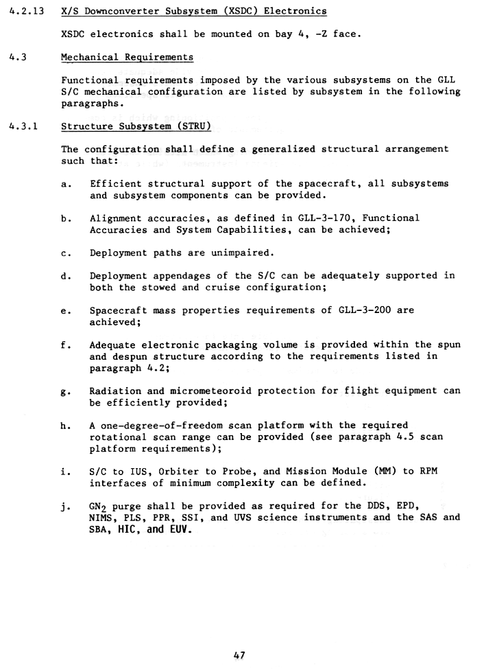
| page 47 | Electronic Packaging Arrangement Cont.: SXDC Mechanical Requirements: STRU |
|
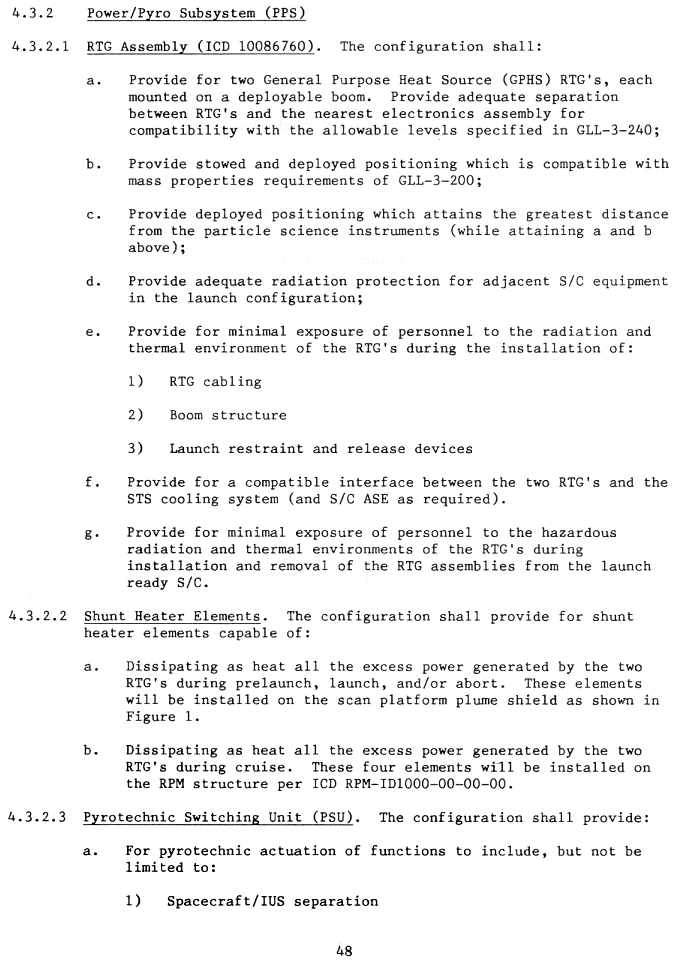
| page 48 | PPS: RTG Assembly, Shunt Heater Elements, PSU | |
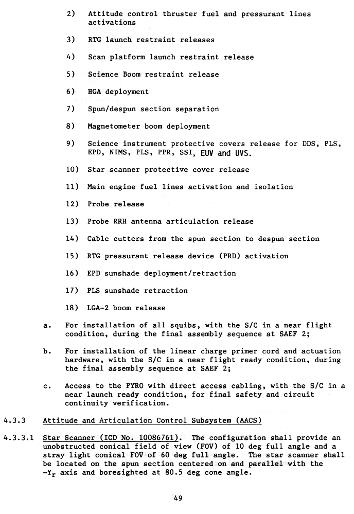
| page 49 | PSU Cont. AACS: Star Scanner |
|
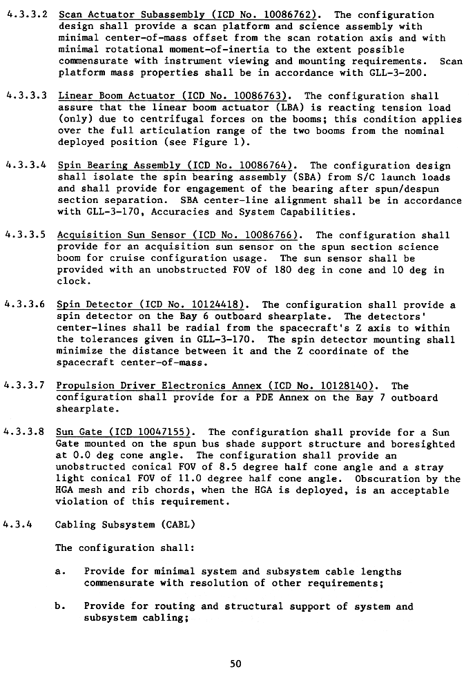
| page 50 | AACS Cont.: Scan Actuator Subassembly, Linear
Boom Actuator, Spin Bearing Assembly, Acquisition Sun Sensor, Spin
Detector, Propulsion Driver Electronics Annes, Sun Gate Cabling Sybsystem (CABL) |
|
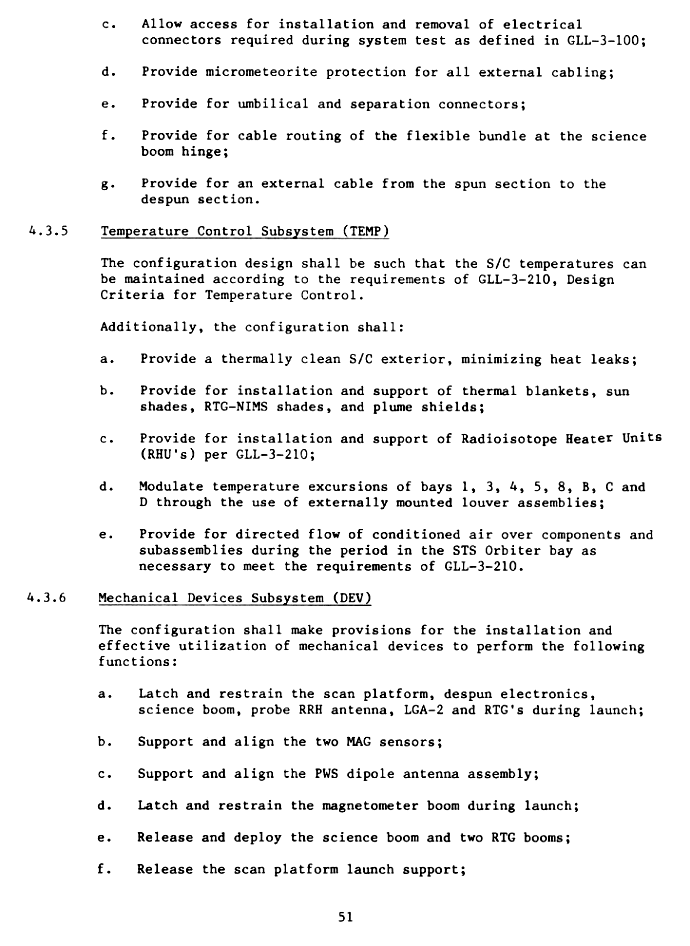
| page 51 | Cabl Cont Temperature Control Subsystem Mechanical Devices Subsystem |
|
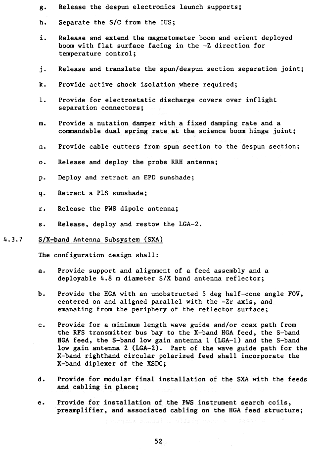
| Mechanical Devices Subsystem Cont. S/X-band Antenna Subsystem (SXA) |
||
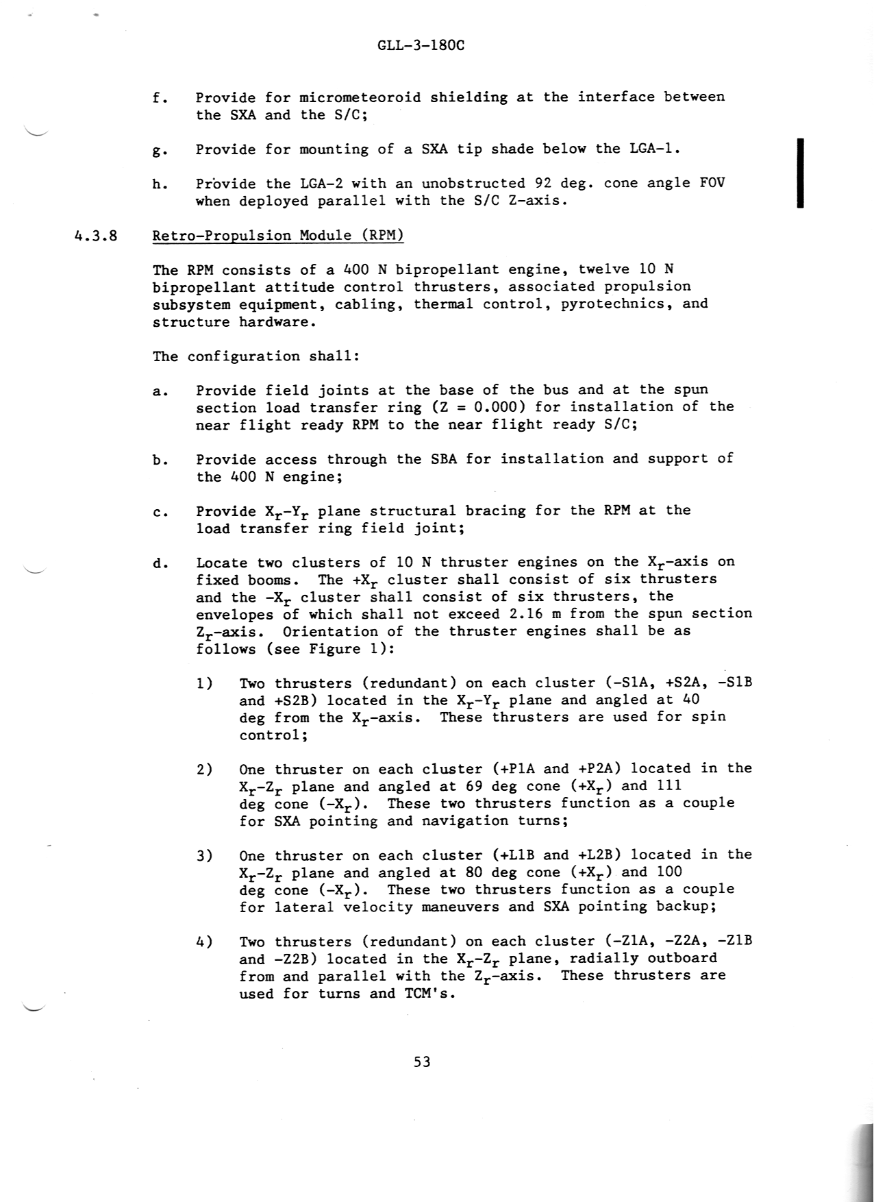
| page 53 | SXA Cont. Retro-Propulsion Module (RPM) |
|
| page 54 | RPM Cont. Probe Heavy Ion Counter (HIC) |
|
| page 55 | Extreme Ultraviolet Subsystem (EUV) Science Requirements |
|
| page 56 | Science Requirements Cont. Near Infrared Mapping Spectrometer Subsystem (NIMS) |
|
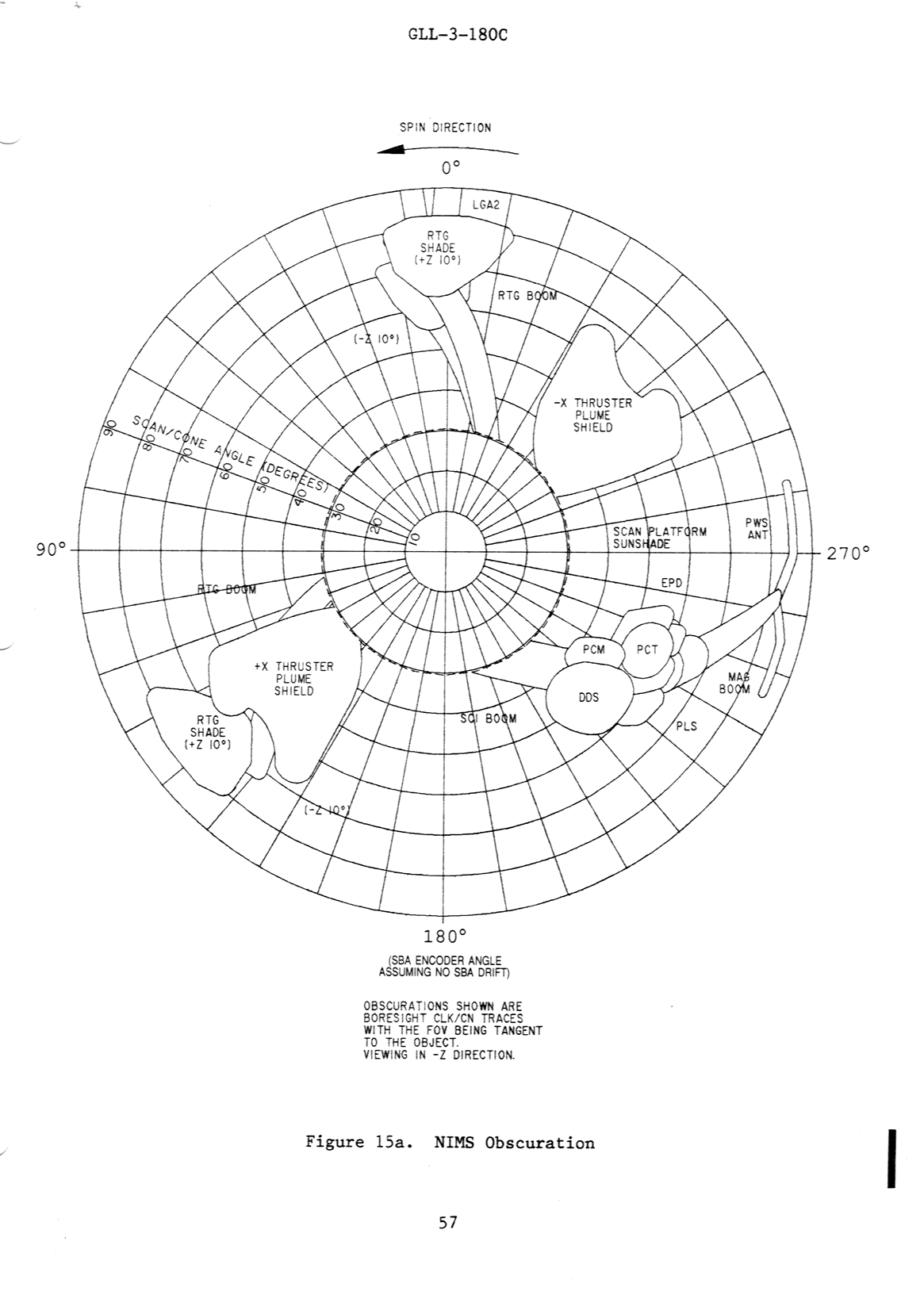
| page 57 | Image showing the NIMS Obscuration | |
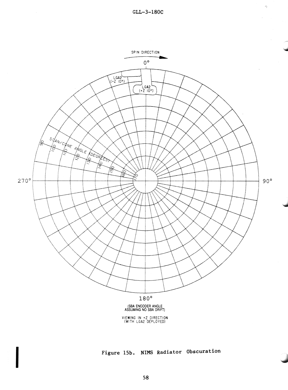
| page 58 | Image showing the NIMS Radiator Obscuration in a +Z direction | |
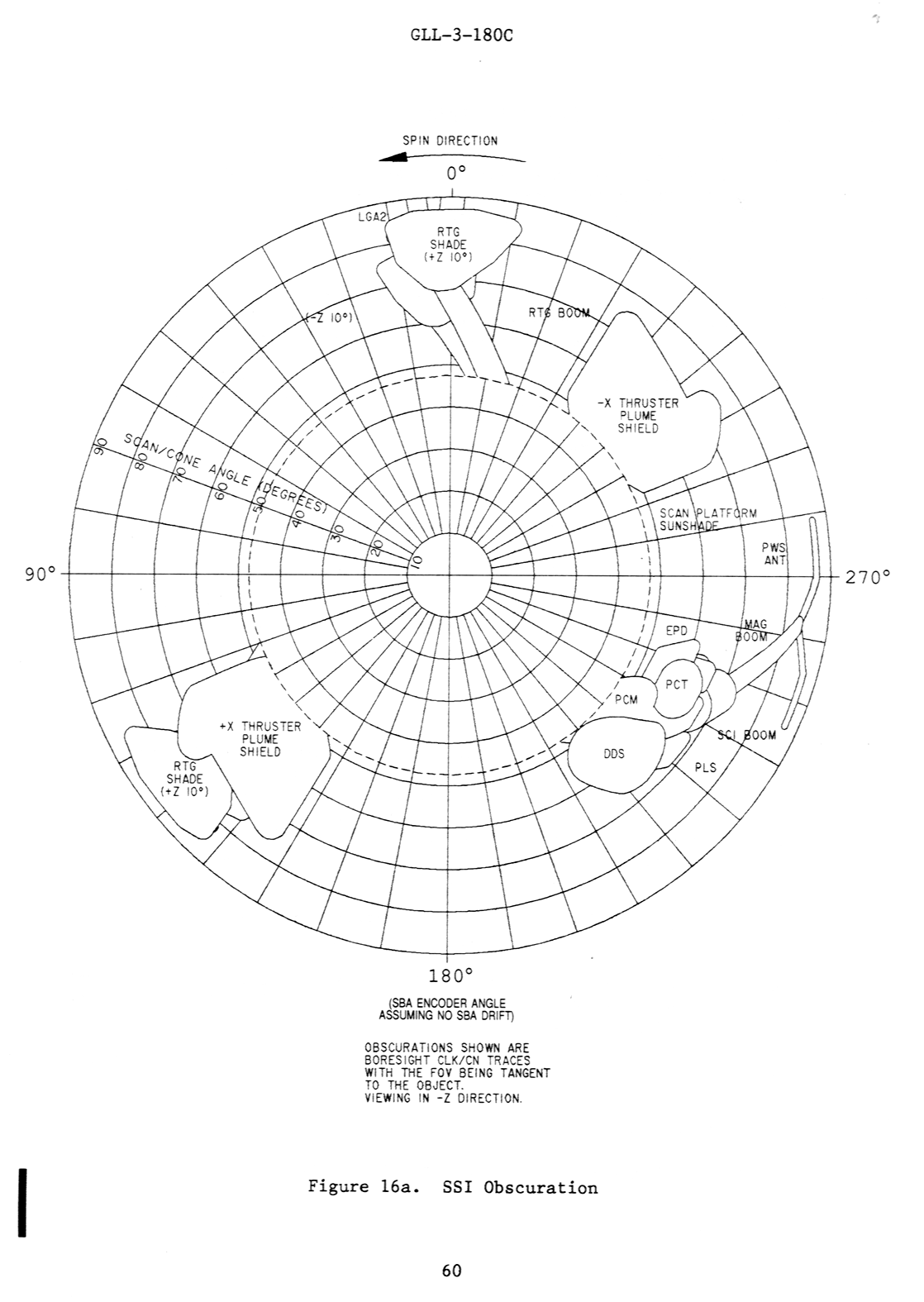
| page 59 | Solar State Imaging Subsystems (SSI) Ultraviolet Spectrometer Subsystems (UVS) |
|
| page 60 | Image Showing SSI Obscuration | |
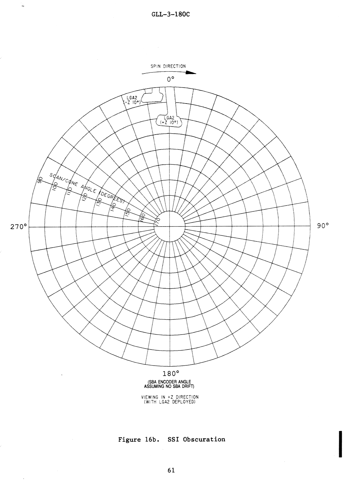
| page 61 | Image Showing SSI Radiator Obscuration in a +Z direction | |
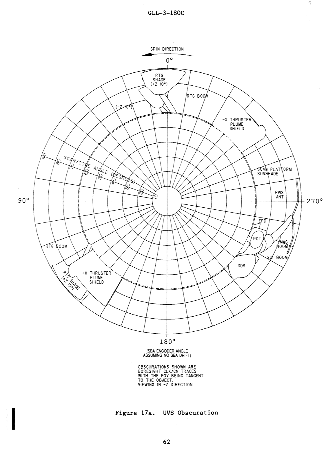
| page 62 | Image Showing UVS Obscuration | |
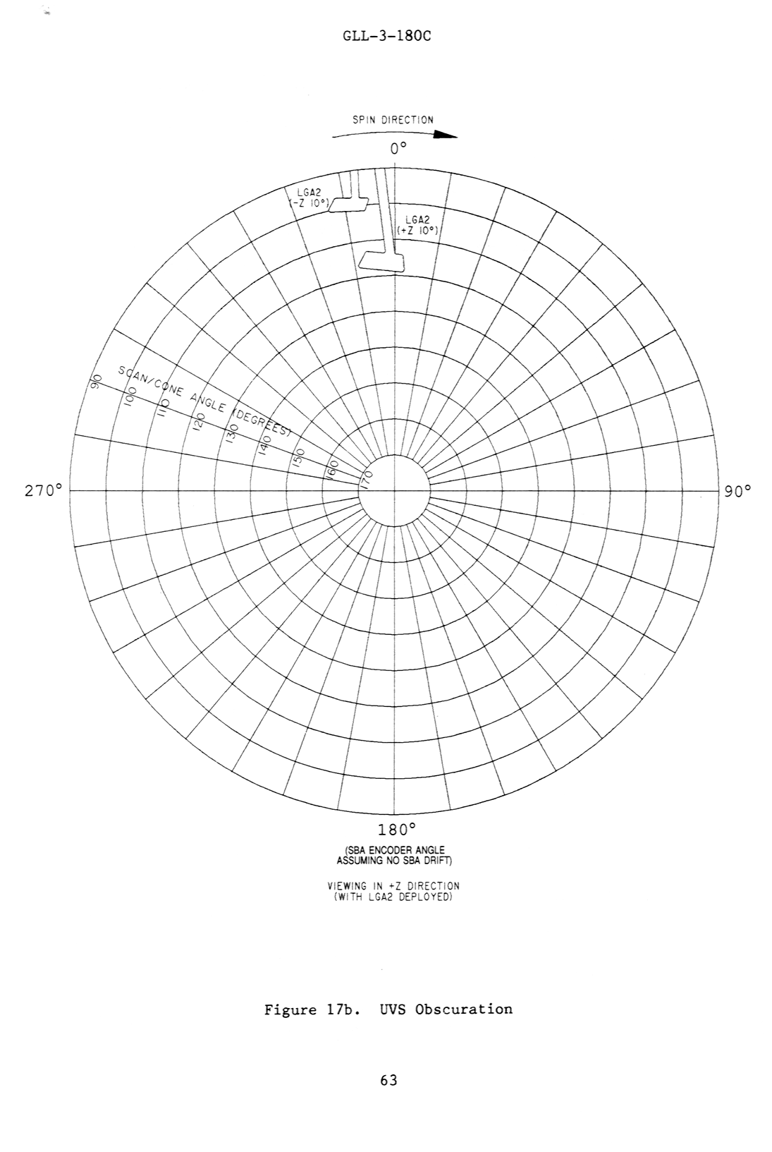
| page 63 | Image Showing UVS Radiator Obscuration in a +Z direction | |
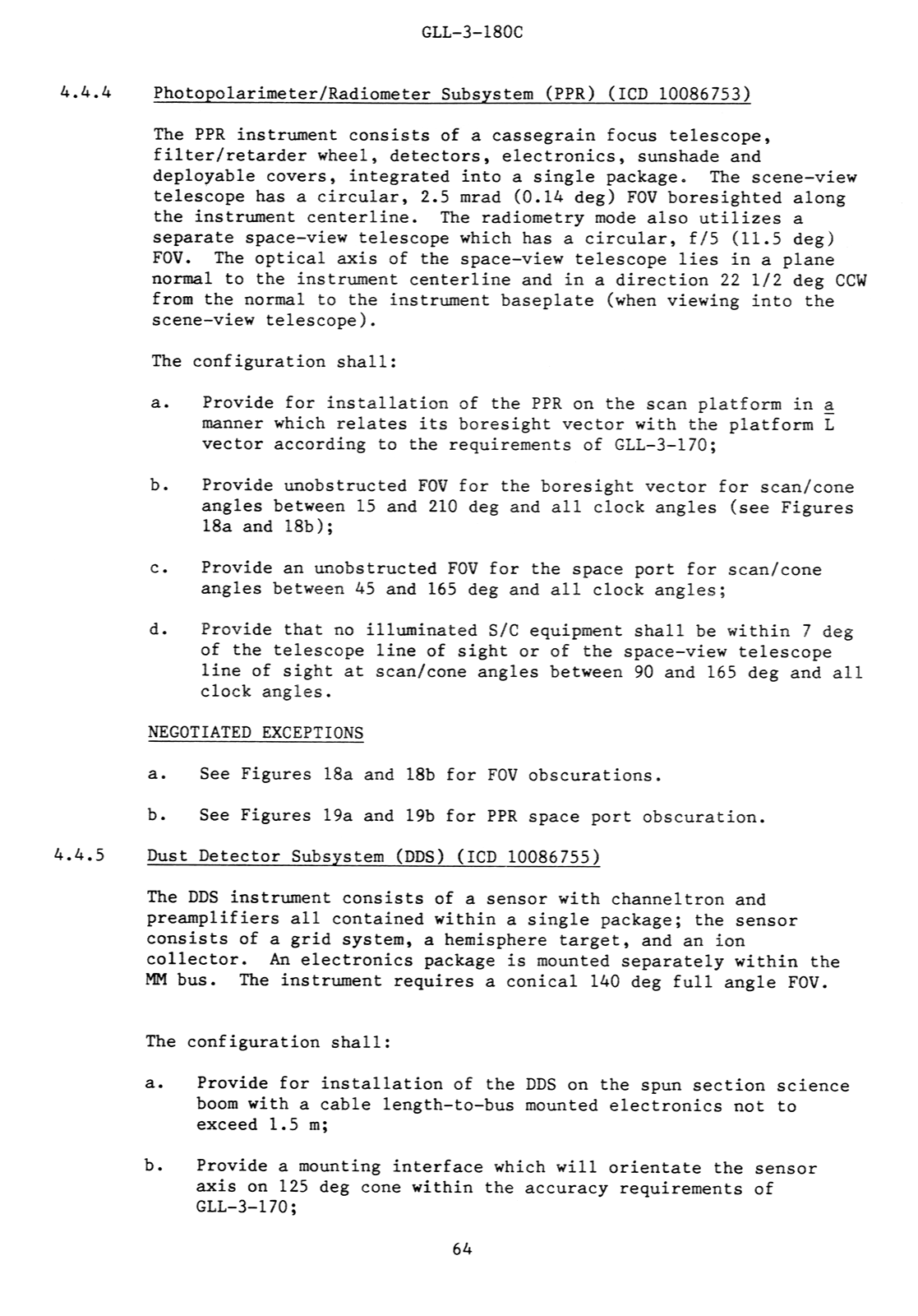
| page 64 | Photopolarimeter/Radiometer Subsystem (PPR) Dust Detector System (DDS) |
|
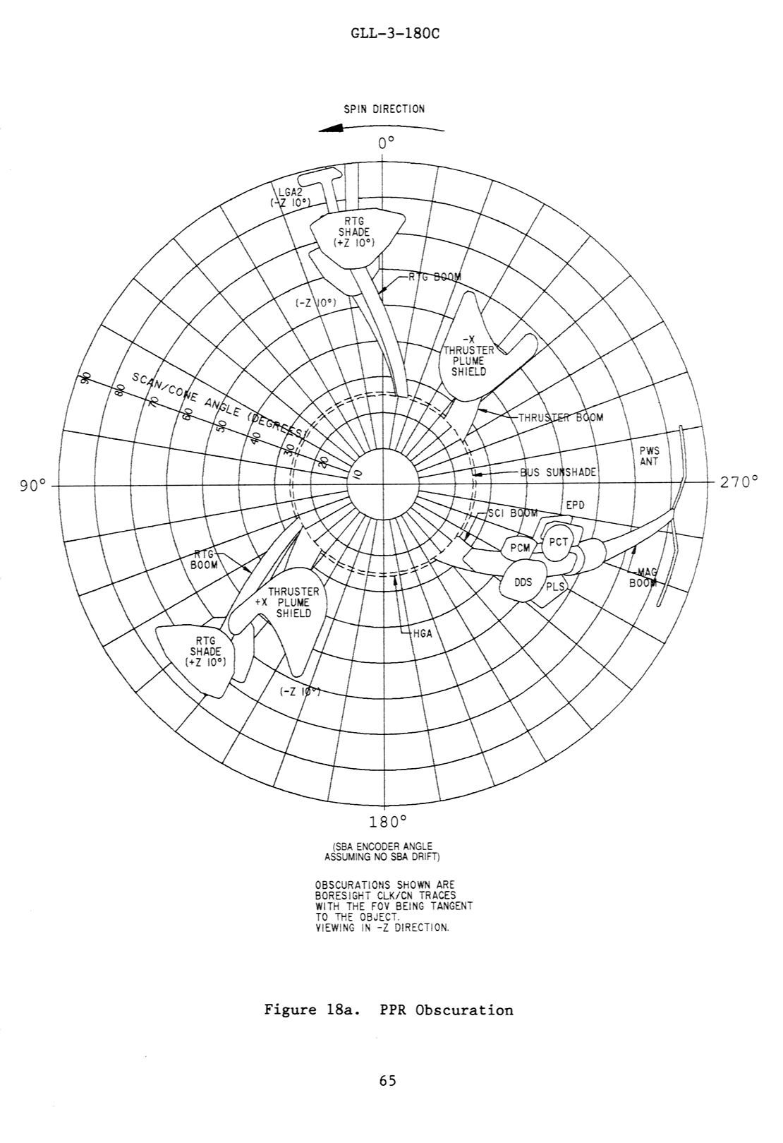
| page 65 | Image Showing the PPR Obscuration | |
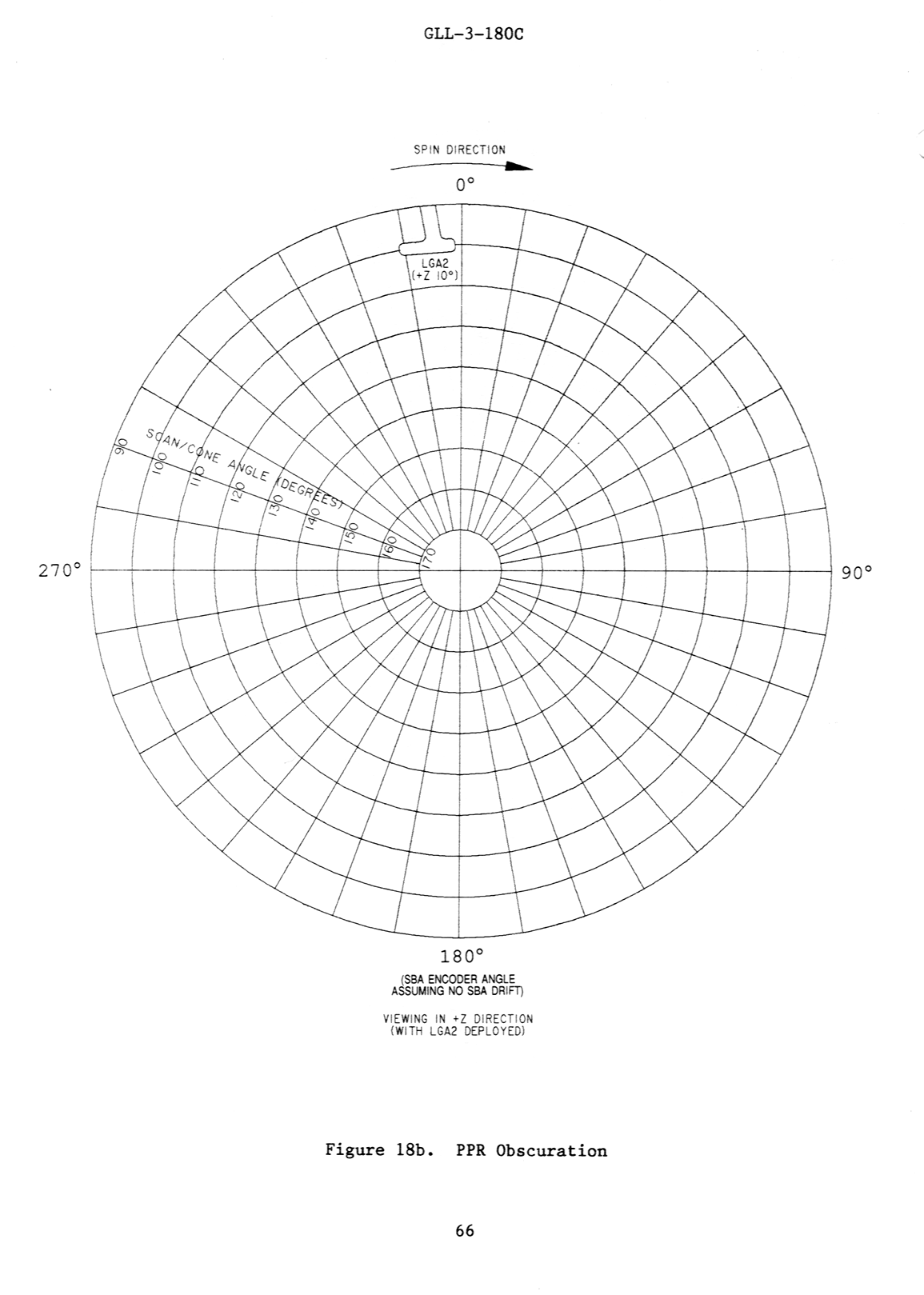
| page 66 | Image Showing the PPR Radiator Obscuration in a +Z direction | |
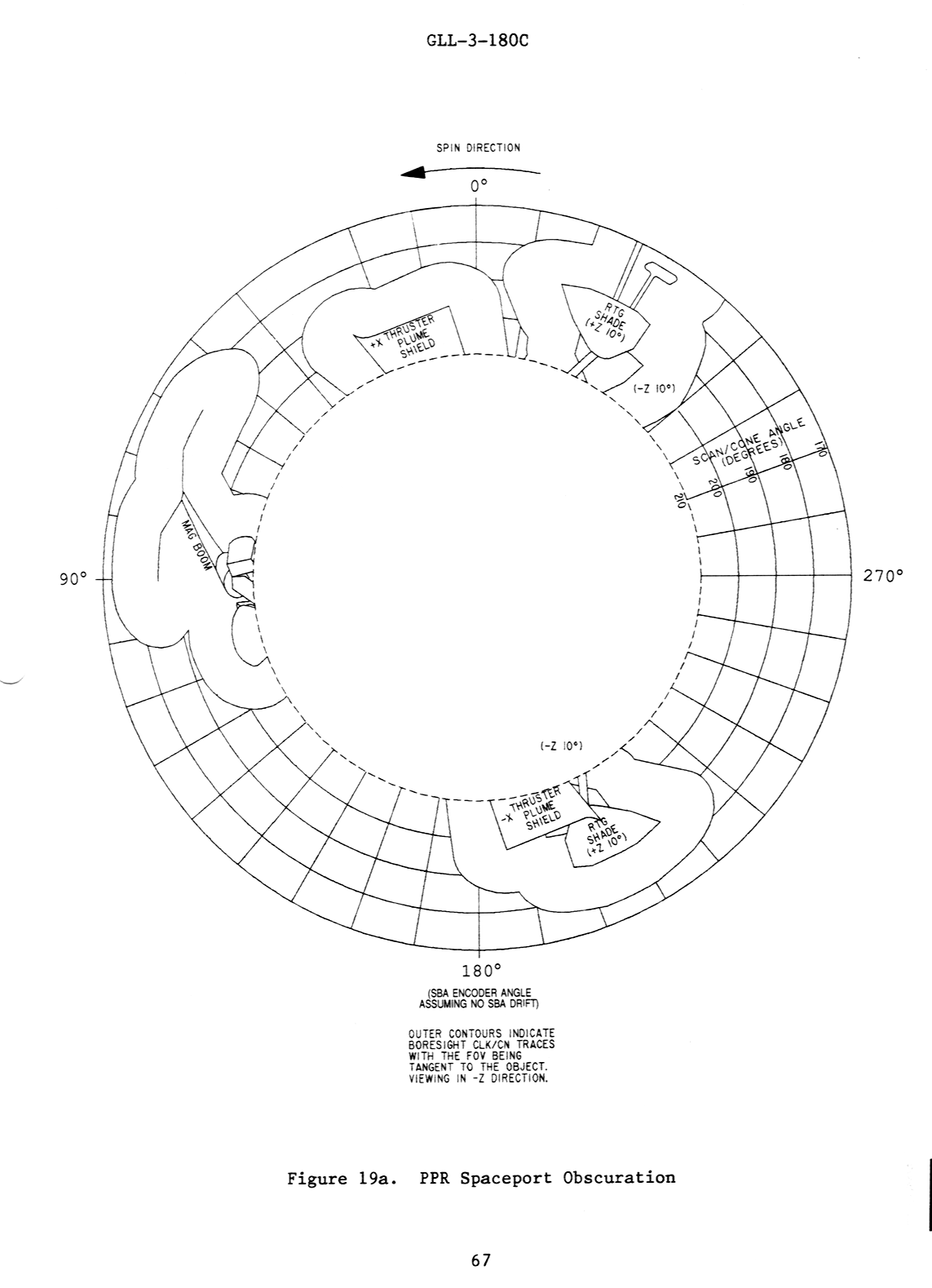
| page 67 | Image Showing the PPR Spaceport Obscuration | |
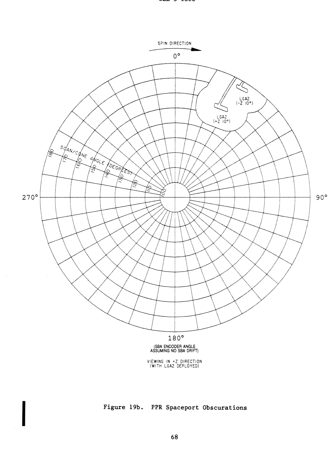
| page 68 | Image Showing the PPR Spaceport Obscurations in a +Z direction | |
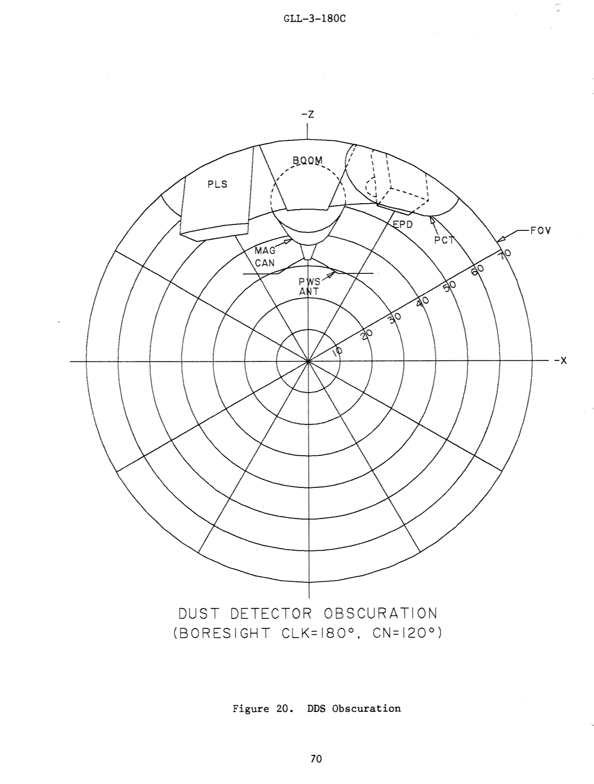
| page 69 | DDS Cont. Plasma Subsystem (PLS) Energetic Particles Detector Subsystem (EPD) |
|
| page 70 | Image Showing the DDS Obscuration | |
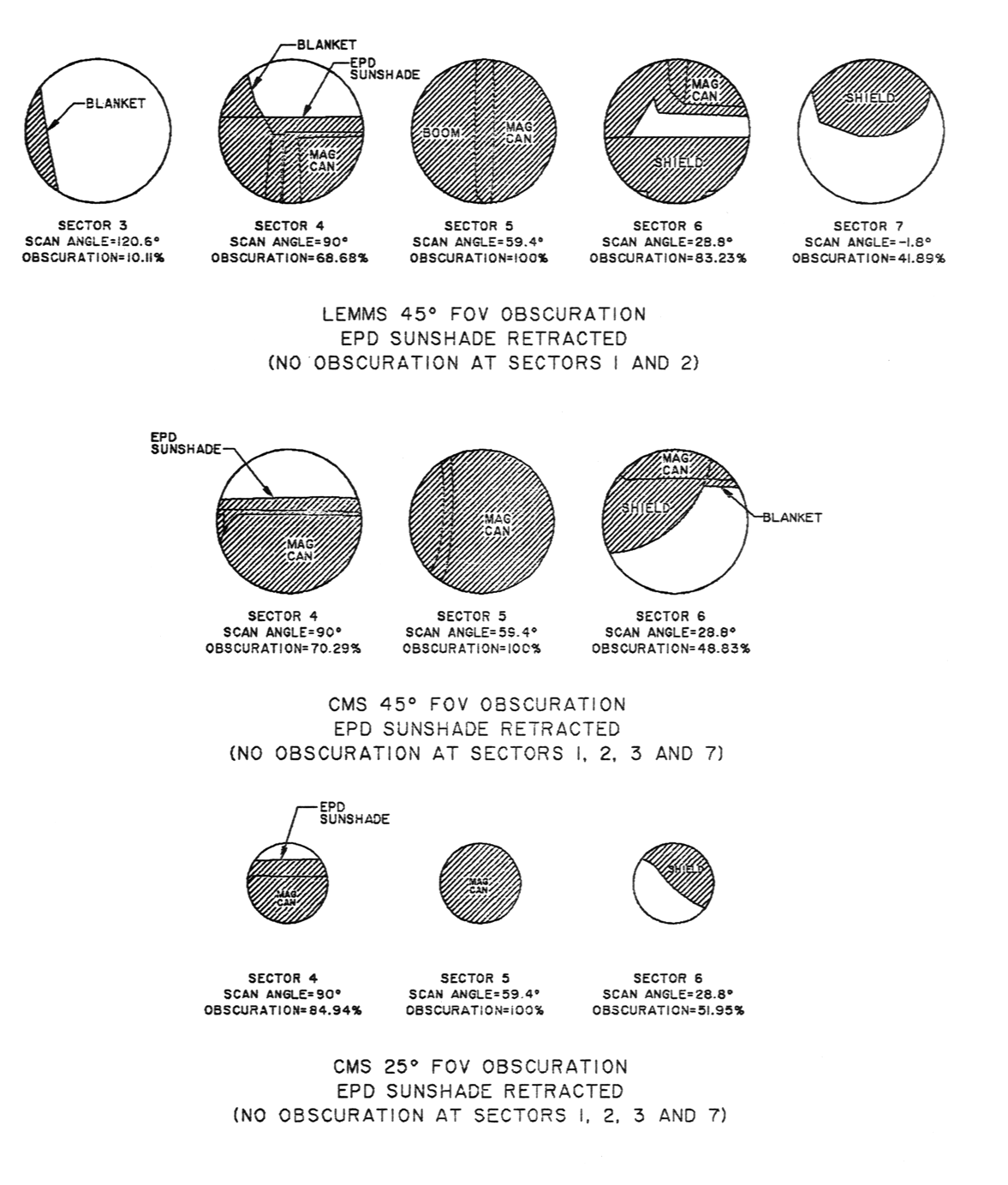
| page 71a | Image of FOV Obscuration with EPD Sunshade Retracted | |
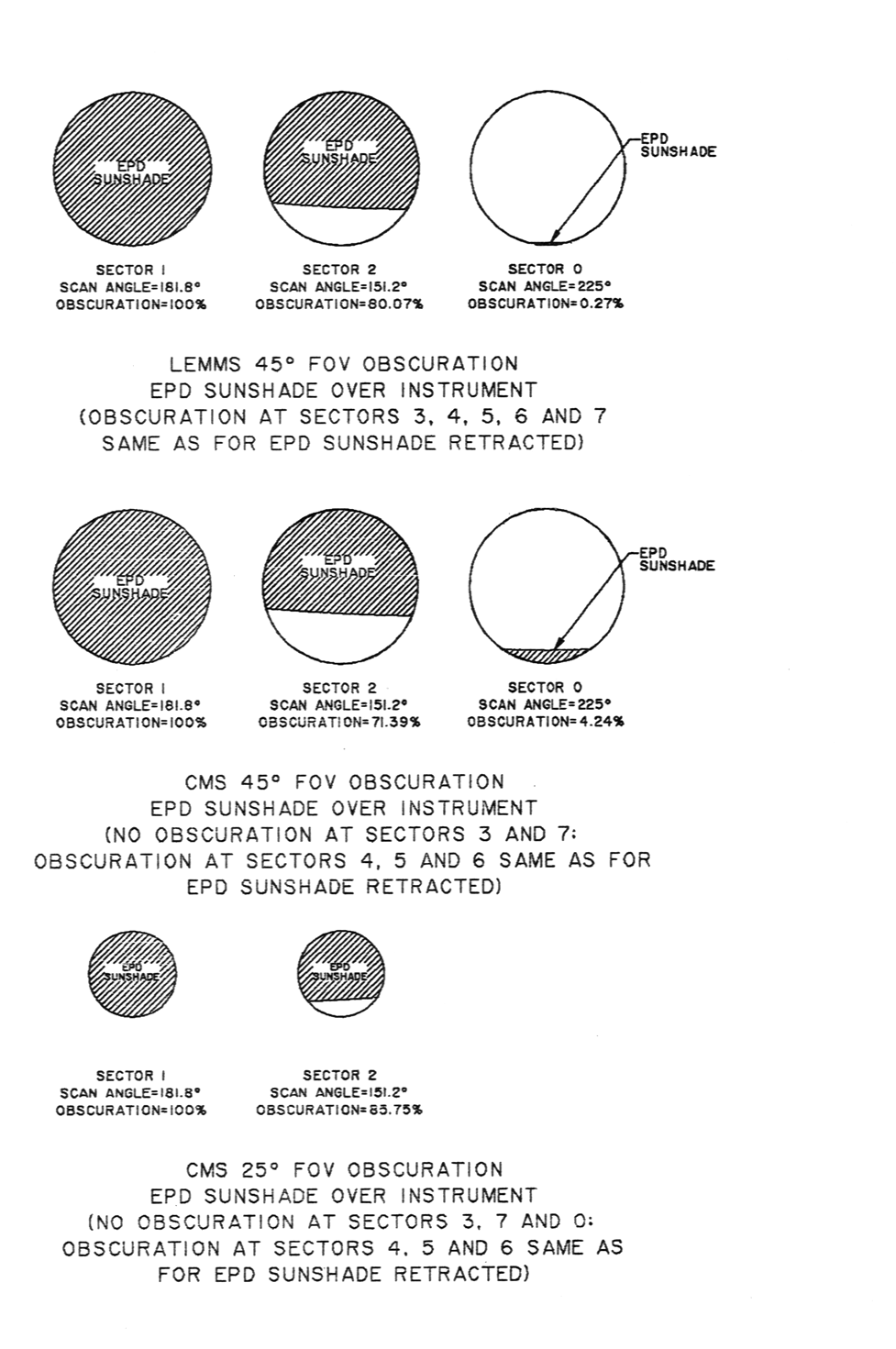
| page 71b | Image of FOV Obscuration with EPD Sunshade Over Inst. | |
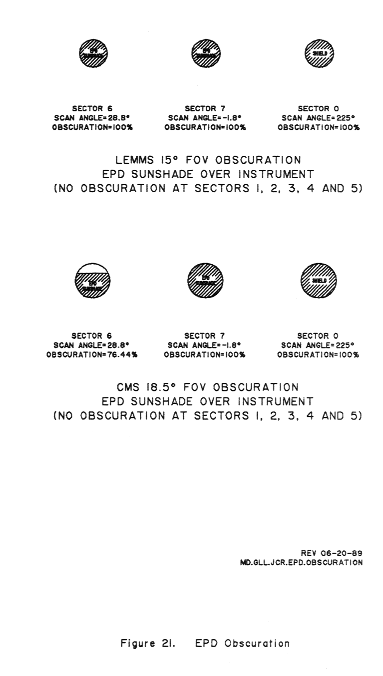
| page 71c | Image of LEMMS 15ş and CMS 18.8ş FOV Obscuration with EPD Sunshade over Inst. | |
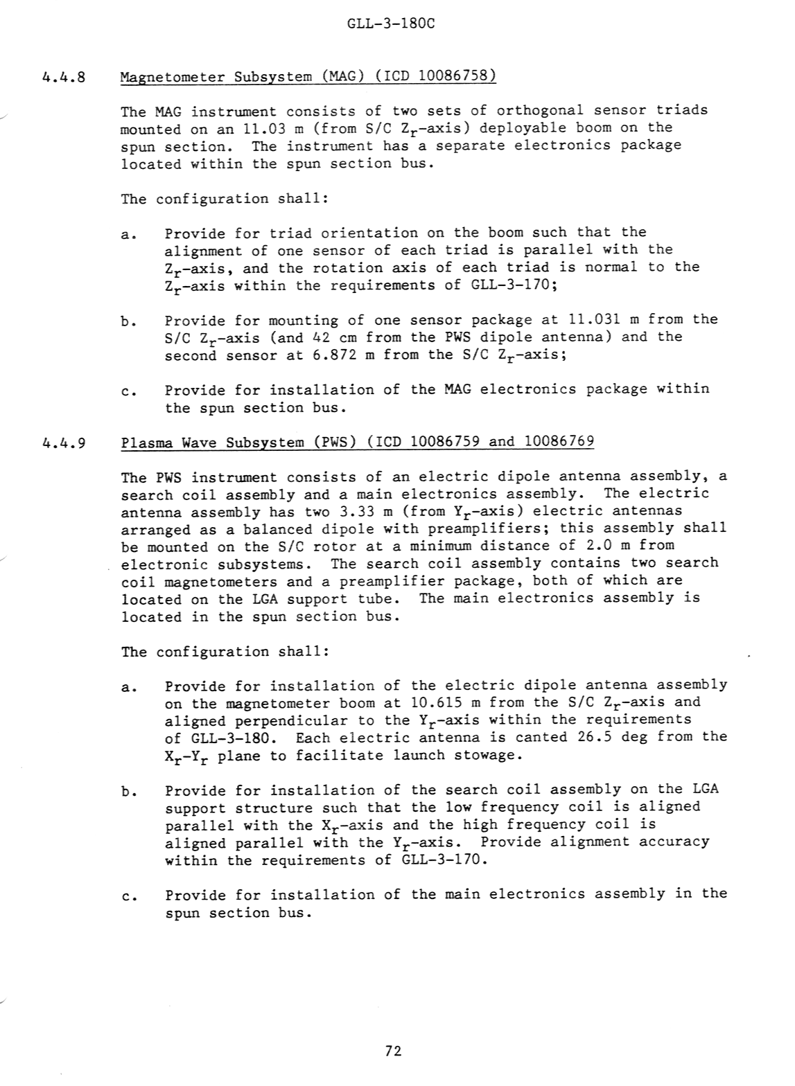
| page 72 | Magnetometer Subsystems (MAG) Plasma Wave Subsystems (PWS) |
|
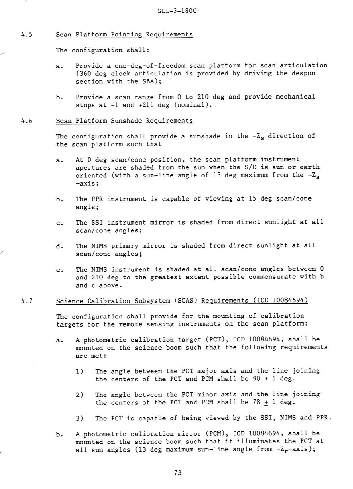
| page 73 | Scan Platform Pointing Requirements Scan Platform Sunshade Requirements Science Calibration Subsystem (SCAS) Requirements |
|
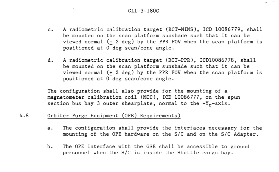
| page 74 | SCAS Cont. Orbiter Purge Equipment (OPE) Requirements |
|
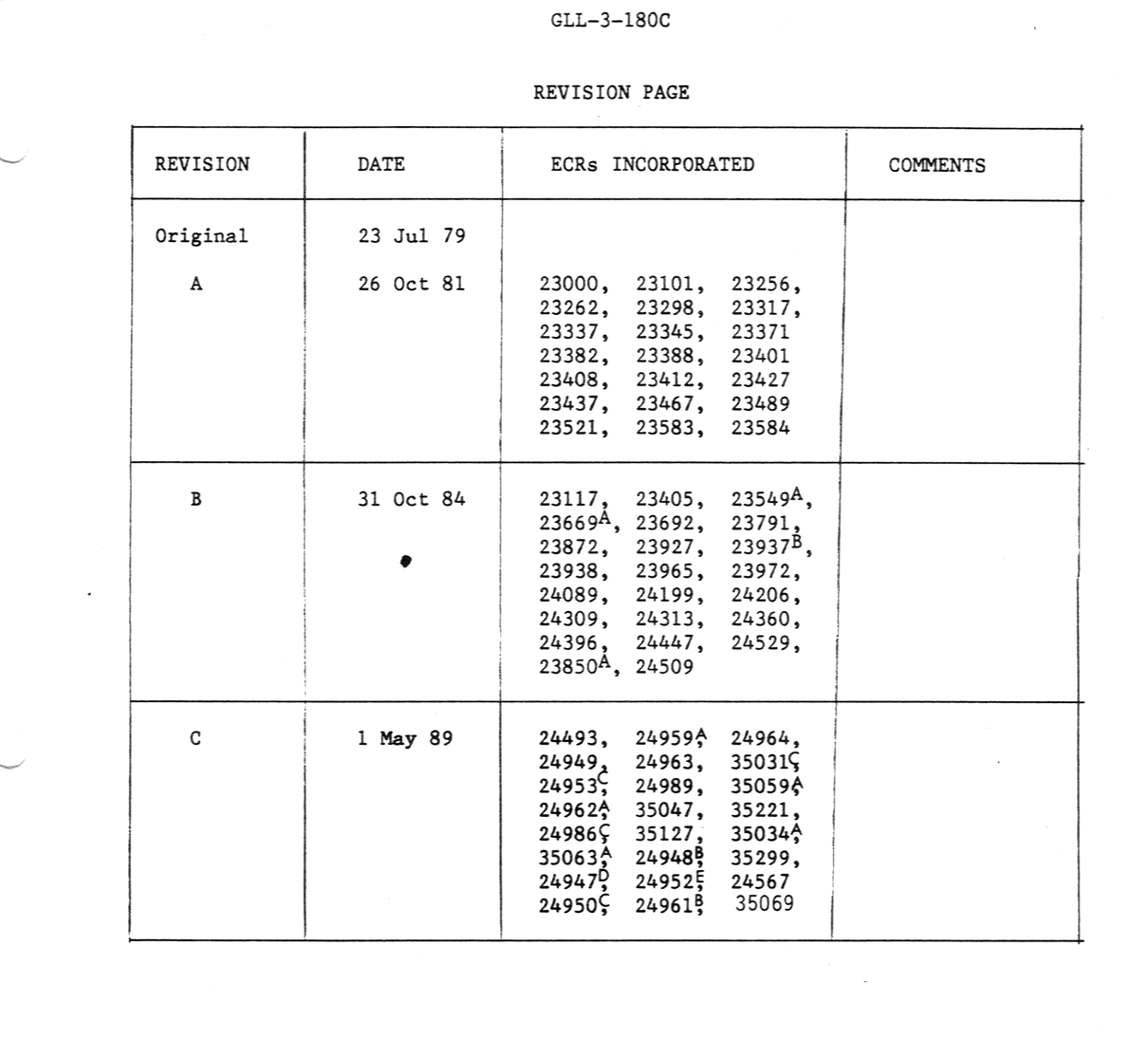
| page 75 | Revision Table | |