Trigger 5A Description
Sequence: C23, C24
Trigger 5A (High Rate Cyclic Mode)
This mode is designed to step through various RPWS high resolution observations
over periods of order 1 hour or longer. Eight different high resolution modes are sampled for
periods of 3 to 9 minutes with one complete cycle taking 1 hour. The cyclic repeats until it
is stopped by the issuance of a new trigger command, typically Trigger 80. The targeted
average data rate (averaged over 1 hour) is 40 kbps, but the true, compressed data rate
realized is closer to 30.5 kbps although this is somewhat data dependent.
Trigger 5A is essentially identical to Trigger 58, but with a higher targeted
bit rate. It achieves this higher bit rate by doubling the size of the 75-KHz WBR
snapshots from 2048 to 4096 samples (every 1/8 sec.), and also by halving the time
between snapshots, from every 1/4 sec. to 1/8 sec., in the HF-WBR modes.
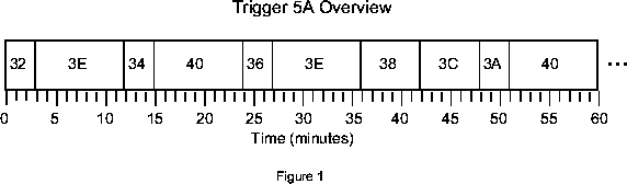
Figure 1 provides an overview of the Trigger 5A cyclic. As can be seen, WBR modes
are alternated with WFR modes. This is primarily to ensure that high rate modes (WBR) are
separated by periods of significantly lower data rate periods (WFR) to minimize non-linear
effects in SSR managment. The peak data rates for the WBR modes are of order 115 kbps
while those of the WFR modes are of order 6 kbps. Specifically, this cyclic collects WBR
data in 25-kHz bands centered on 8.025 MHz, 1.025 MHz, and 125 kHz, in the 75-kHz and
10.5-kHz baseband modes interspersed with periods of 2.5-kHz and 26-Hz WFR modes. The
user is referred to individual descriptions of these underlying triggers (as listed in Figure 1)
for details on each of these.
| Step |
Receiver |
Frequency |
Duration |
| Trigger 32 |
HF-WBR |
8.025 MHz |
3 minutes |
| Trigger 34 |
HF-WBR |
1.025 MHz |
3 minutes |
| Trigger 36 |
HF-WBR |
0.125 MHz |
3 minutes |
| Trigger 38 |
WBR |
0 - 75 KHz |
6 minutes |
| Trigger 3A |
WBR |
0 - 10.5 KHz |
3 minutes |
| Trigger 3C |
HFR |
Max. Spectral Res. |
6 minutes |
| Trigger 3E |
WFR |
0 - 2.5 KHz |
9 minutes |
| Trigger 40 |
WFR |
0 - 25 Hz |
9 minutes |
Low Rate Measurements During the Trigger 5A Cyclic

     Underlying Trigger 5A, the RPWS continues to collect spectral survey data over the
entire RPWS frequency range (1 Hz - 16.1 MHz) as continuously as possible, provided the
limitations of the RPWS hardware and software limits.  The survey data are collected as
follows:

1.  Low Frequency Receiver: This covers the frequency range from 1 to 25 Hz using a 2-
channel mode of the WFR, specifically using Ex (dipole) and Bx sensors.  One waveform
series of 512 samples are collected every 32 seconds simultaneously for each of these two
sensors.  The waveform is spectrum analyzed on board and a 28-channel(?) quasi-logarithmic
spectrum is constructed by binning adjacent Fourier components.  The initial AGC gain is set
to20 dB for Ex and 30 dB for Bx and is updated after every waveform series (?).  The AGC
set point is 17, 85 (what does this mean?).  These data are collected during the Trigger 3A,
3C, and 3E elements of the cyclic, (10.5-kHz WBR, high resolution HFR, and 2.5-kHz WFR).
The raw data required to construct these channels are collected in Trigger 40, but are routed
directly to the ground and can be filled in for this mode in ground processing, if required.
The data cannot be collected in triggers 32, 34, 36, or 38 (the HF-WBR or 75-kHz WBR
modes) because of hardware limitations.

2.  Medium Frequency Receiver:   The spectral data for the frequency range from 25 Hz to
12 kHz are collected by the MFR continuously throughout Trigger 5A using the Ew and Bz
sensors.  A spectrum from the Ew sensor is collected during one 32-second period and the Bz
spectrum is collected during the following 32-second period.

3.  High Frequency Receiver: When the HFR is not required to do otherwise, it is set to the
so-called composite mode survey mode during Trigger 5A.  This is the case for Triggers 38,
3A, 3E, and 40.    This mode is defined by:

          Correlations     Channels        Integ.                Size Frequency
Band Ant. Auto-  Cross-    per Band   df   Period    Rep   Steps kHz  Start - Stop
---- ---- -----  ------    --------   --   ------    ---   ----- ---- ------------
ABC  2E   y         y        16       n    1000      1                3.6-319 kHz
H1   2E             y         2       n    80        1     30    50   325k-1.8MHz
H2   1E                       1       n    20        1     72    200  1.8M-16MHz

Bands ABC require 3.16 sec to complete, H1 requires 2.524 sec, and H2 requires 1.461 sec
for a total of 7.25 sec per sweep.

For the HF-WBR modes the HFR is required to be in freeze mode at the frequency being
analyzed by the HF-WBR.  During these times, the HFR is in millisecond mode, collecting
AGC values once per millisecond for use with the HF-WBR data.  The AGC values are
collected in sets of 2048 samples taken over 2.12 seconds.  There is a __ second gap between
each AGC value set.  The HF-WBR modes are interrupted once per minute to collect one
HFR sweep in the composite mode survey described above.

Finally, the HFR is run in its highest spectral resolution mode during Trigger 3C:

          Correlations     Channels        Integ.                Size Frequency
Band Ant. Auto-  Cross-    per Band   df   Period    Rep   Steps kHz  Start - Stop
---- ---- -----  ------    --------   --   ------    ---   ----- ---- ------------
ABC  2E   y      y         32         n    1000      1                3.6-319 kHz
H1   2E          y         8          n    80        1     157   25   125k-4MHz
H2   1E                    8          n    80        1     243   50   4M-16.1MHz

Bands ABC require 3.12 sec to complete, H1 requires 14.3 sec, and H2 requires 21.75 sec for
a total of 39.25 sec per sweep.