Space Science Reviews 21 (1977) 289-308. All Rights
Reserved.
Copyright © 1977 Kluwer Academic Publishers, Dordrecht, Boston,
London.
Reprinted with permission of Kluwer Academic Publishers.
This material is posted here with permission of Kluwer Academic Publishers (Kluwer). Such permission of Kluwer does not in any way imply Kluwer endorsement of any PDS product or service. Internal or personal use of this material is permitted. However, permission to reprint/republish this material for advertising or promotional purposes or for creating new collective works for resale or redistribution must be obtained from Kluwer.
By choosing to view this document, you agree to all provisions of the copyright laws protecting it.
A PLASMA WAVE INVESTIGATION FOR THE VOYAGER MISSION
FREDERICK L. SCARF
TRW Defense & Space Systems Group, One Space Park, Redondo Beach, Calif. 90278, U.S.A
and
DONALD A. GURNETT
Department of Physics & Astronomy, University of Iowa, Iowa City, Iowa 52242, U.S.A.
(Received 24 May, 1977)
Abstract. The Voyager Plasma Wave System (PWS) will provide the first direct information on wave-particle interactions and their effects at the outer planets. The data will give answers to fundamental questions on the dynamics of the Jupiter and Saturn magnetospheres and the properties of the distant interplanetary medium. Basic planetary dynamical processes are known to be associated with wave-particle interactions (for instance, solar wind particle heating at the bow shock, diffusion effects that allow magnetosheath plasma to populate the magnetospheres, various energization phenomena that convert thermal plasma of solar wind origin into trapped radiation, and precipitation mechanisms that limit the trapped particle populations). At Jupiter, plasma wave measurements will also lead to understanding of the key processes known to be involved in the decameter bursts such as the cooperative mechanisms that yield the intense radiation, the observed millisecond fine-structure, and the Io modulation effect. Similar phenomena should be associated with other planetary satellites or with Saturn’s rings. Local diagnostic information (such as plasma densities) will be obtained from wave observations, and the PWS may detect lightning whistler evidence of atmospheric electrical discharges. The Voyager Plasma Wave System shares the 10-meter PRA antenna elements, and the signals are processed with a 16-channel spectrum analyzer, covering the range 10 Hz to 56 kHz. At selected times during the planetary encounters, the PWS broadband channel will operate with the Voyager video telemetry link to give complete electric field waveforms over the frequency range 50 Hz to 10 kHz.
1. Introduction
The Voyager plasma wave system (PWS) will measure electric field components of local plasma waves over the frequency range extending from 10 Hz to 56 Hz. The PWS shares the two extendible 10-meter electric antenna elements provided by the planetary radio astronomy (PRA) investigators, but the two groups use these sensors in different ways. For the radio measurements the antennas are connected as a pair of orthogonal monopoles, while the PWS investigators use these same elements to form a balanced electric dipole. In the normal format, the plasma wave signals are processed with a simple 16-channel spectrum analyzer, and at the planetary encounters this system will provide a full spectral scan every four seconds. The PWS also has a broadband amplifier that will utilize the Voyager video telemetry link to give electric field waveforms (frequency range 50 Hz to 10 kHz) at selected times during planetary encounters.
The Voyager plasma wave investigation is designed to provide key information on the wave-particle interaction phenomena that control important aspects of the plasma dynamics in the magnetospheres of Jupiter and Saturn. It is well known that wave-particle interactions play extremely important roles at Earth, and it is also known that the dynamics of at least the inner magnetosphere of Jupiter is conceptually similar to that of Earth, despite the vast difference in size and in energy of the trapped particles. In addition, the satellites of Jupiter and Saturn provide important localized sources of plasma and field-aligned currents, and they must significantly affect the trapped particle populations. Pioneer 10, 11 measurements indicate that in the inner region of Jupiter the trapped electron fluxes are near the stable limit set by whistler mode and half- gyrofrequency harmonic mode wave-particle interactions; however, the ion fluxes are probably controlled by other instabilities (ion cyclotron, drift wave, loss cone, etc.). The plasma waves cause pitch- angle diffusion, and the precipitating electrons and ions must significantly affect the ionospheric properties and influence ionosphere-magnetosphere coupling. It is also expected that some kinds of enhanced precipitation and wave-induced anomalous conductivity effects develop along field-lines threading the inner satellites, and strong plasma wave radiation field coupling must account for the intense levels of decametric emissions.
Studies of wave-particle interaction phenomena in the outer
magnetospheres of Jupiter and Saturn are also of great importance.
These outer regions should be dominated by the high-
![]() [=4
[=4![]() N
N
![]() T/B2] plasma spun out by
centrifugal forces, and here wave-particle interactions can provide
local acceleration; they can affect particle diffusion; and they can
lead to field-line merging. If the magnetospheric plasma at Jupiter or
Saturn flows radially outward to form a planetary wind, wave-particle
interactions should lead to a second collisionless shock within the
magnetopause. Other relevant wave-particle interactions involve
whistlers generated by atmospheric lightning, and electron plasma
oscillations associated with suprathermal particles in the upstream
solar wind.
T/B2] plasma spun out by
centrifugal forces, and here wave-particle interactions can provide
local acceleration; they can affect particle diffusion; and they can
lead to field-line merging. If the magnetospheric plasma at Jupiter or
Saturn flows radially outward to form a planetary wind, wave-particle
interactions should lead to a second collisionless shock within the
magnetopause. Other relevant wave-particle interactions involve
whistlers generated by atmospheric lightning, and electron plasma
oscillations associated with suprathermal particles in the upstream
solar wind.
The fundamental roles of wave-particle interactions and plasma instabilities at Jupiter have been discussed in recent reviews by Coroniti (1975), Goertz (1976), Scarf (1976), and Kennel and Coroniti (1977). Scarf (1975) recently speculated on the structure of Saturn’s magnetosphere, and in the context of a Uranus magnetosphere configuration of the novel type discussed by Kennel (1973) and by Siscoe (1975), it is anticipated that the Voyager plasma wave investigation can also provide unique and valuable information on wave-particle interaction phenomena near Uranus.
In this report we first present some background information on plasma waves and magnetospheric dynamics, with examples drawn from near-Earth observations. This section is followed by a discussion of specific outer planet science objectives, and a summary of the science rationale for the Voyager PWS design. The instrument details are summarized in the following section.
2. Background
Extensive laboratory studies and many theoretical analyses show
that waves play dominant roles in all non-equilibrium plasma systems
(see for instance, Stix, 1962; Montgomery and Tidman, 1964; Sagdeev and Galeev, 1969). In particular, when
the plasma is dilute and cool, ordinary coulomb collisions are
unimportant and wave-particle interactions provide the scattering and
acceleration mechanisms that govern the dynamics. As noted above,
turbulent wave-particle scattering leads to an effective conductivity
and resistive-type heating; resonant wave-particle interactions give
rise to acceleration similar to that in a cyclotron; and waves also
allow diffusion that can be directly associated with particle
energization (i.e., cross L diffusion with conservation of
magnetic moment, µ=mv
![]() 2/B, gives v
2/B, gives v
![]() ~B1/2). Waves also cause diffusion in
pitch angle and particle precipitation (see Fredricks, 1975, for a recent summary). In all
cases, the most significant interactions involve waves that are
strongly emitted and absorbed by the plasma ions and electrons. The
local interactions of importance are associated with waves having
phase speeds comparable to plasma particle speeds, the
‘radiation’ mechanism is essentially a generalized Cerenkov
process, and the spectral region where the strong wave absorptions and
emissions occur is called the plasma wave region.
~B1/2). Waves also cause diffusion in
pitch angle and particle precipitation (see Fredricks, 1975, for a recent summary). In all
cases, the most significant interactions involve waves that are
strongly emitted and absorbed by the plasma ions and electrons. The
local interactions of importance are associated with waves having
phase speeds comparable to plasma particle speeds, the
‘radiation’ mechanism is essentially a generalized Cerenkov
process, and the spectral region where the strong wave absorptions and
emissions occur is called the plasma wave region.
Plasma wave modes of importance in magnetospheric physics are
related to the electron and ion gyrofrequencies,
fc±=eB/2
![]() m±c, and to the electron and
ion plasma frequencies, fp±=
(4
m±c, and to the electron and
ion plasma frequencies, fp±=
(4![]() Ne2/m±)1/2
/2
Ne2/m±)1/2
/2![]() , where N is the plasma density and
B is the local magnetic field strength. As an example of the
spectral range for the characteristic resonant frequencies, when
N = 5 cm-3 and B = 5 gamma (typical upstream
solar wind conditions near 1 AU), these expressions give
fp-=20 kHz,
fp+=470 Hz,
fc-=140 Hz, and
fc+ = 0.076 Hz. These plasma wave
modes can also be categorized as generalized electromagnetic waves
(having both E and B wave components), or as
electrostatic oscillations (similar to compressional sound waves, with
space charge variations that produce only electric field wave
components). For instance, the whistler mode (f
, where N is the plasma density and
B is the local magnetic field strength. As an example of the
spectral range for the characteristic resonant frequencies, when
N = 5 cm-3 and B = 5 gamma (typical upstream
solar wind conditions near 1 AU), these expressions give
fp-=20 kHz,
fp+=470 Hz,
fc-=140 Hz, and
fc+ = 0.076 Hz. These plasma wave
modes can also be categorized as generalized electromagnetic waves
(having both E and B wave components), or as
electrostatic oscillations (similar to compressional sound waves, with
space charge variations that produce only electric field wave
components). For instance, the whistler mode (f
![]() fc-) is
electromagnetic, but ion sound waves (f
fc-) is
electromagnetic, but ion sound waves (f
![]() fp+) and electron
plasma oscillations (f
fp+) and electron
plasma oscillations (f![]() fp-
) are electrostatic.
fp-
) are electrostatic.
Figure 1 shows some examples of natural plasma waves observed near Earth using the broadband or waveform channels of the plasma wave instruments on the OGO-5 and IMP-6 spacecraft. As shown in the top panels of the figure, the electron plasma frequency is significant in two distinct ways. Suprathermal electrons in the region upstream from the bow shock lose energy by radiating narrowband electrostatic waves (upper left) at f=fp- (Scarf et al., 1971). In addition, fp- is a well-known critical frequency for electromagnetic waves in the sense that the usual free space electromagnetic modes can be transmitted through a plasma if f>fp-, whereas for f<fp- they cannot propagate. The cutoff of outer magnetosphere electromagnetic noise at the plasma frequency is shown in the upper right panel of Figure 1. Measurement of this cutoff frequency provides an excellent technique for determination of the plasma density; in fact, since this technique is based on analysis of electromagnetic wave modes having wavelengths in the kilometer range, the presence of the spacecraft and its plasma sheath is unimportant, and observation of the fp--cutoff provides an absolute and sheath-independent evaluation of the total plasma density (Gurnett and Frank, 1974).
Wave investigations in Earth orbit have also demonstrated that two general classes of wave-particle interactions are of great importance for magnetospheric dynamics, and these measurements are illustrated in the other panels of Figure 1. Electromagnetic and electrostatic plasma instabilities give rise to relatively narrow- banded spontaneous emissions (e.g., ELF hiss, chorus, three-halves noise, ion cyclotron and ion-plasma-frequency turbulence) that can scatter trapped particles into the loss cone, leading to modified pitch-angle distributions, stable trapping limits, diffuse aurora, proton precipitation events, etc. The current-driven plasma instabilities generate intense impulsive ion acoustic or Buneman mode turbulence that provides very effective energy transfer (via the anomalous conductivity mechanism) at the bow shock and in regions where strong field-aligned currents are observed.
In all cases, the plasma wave observations, in conjunction with measurements from the energetic particle detector, the plasma probe and the magnetometer, provide quantitative information needed to evaluate effective transport coefficients associated with the wave- particle interactions, as indicated by the following examples:
Anomalous Conductivity. At the collisionless bow shock, the
radial outflow shock, at plasma boundaries, and on field lines
threading the satellites, strong currents flow and the two-stream
instability should produce intense electrostatic turbulence in the ion
acoustic mode, with f ![]() fp+, and
V(phase)=
fp+, and
V(phase)=![]() /k
/k
![]()
![]() (
(
![]() T-/m+). For this type
of interaction, the wave-particle scattering can be described in terms
of an anomalous electrical conductivity
T-/m+). For this type
of interaction, the wave-particle scattering can be described in terms
of an anomalous electrical conductivity
![]() =j/E(DC)=Ne2/m
=j/E(DC)=Ne2/m
![]() (eff), (Papadopoulos,
1977) where
(eff), (Papadopoulos,
1977) where
![]() (eff)
(eff)
![]() (2
(2![]() 3)1/2fp-[
3)1/2fp-[![]() 0E2(wave)/2N
0E2(wave)/2N
![]() T]. (1)
T]. (1)
The resistive heating associated with this interaction is very
effective in producing the shock dissipation and particle
acceleration, and we plan to use the observations to evaluate
![]() (eff) and to study the effect of this important
interaction.
(eff) and to study the effect of this important
interaction.
Whistler Mode Scattering. The simple Kennel-Petschek theory (1966) predicts that electrons with resonant energy
ER=(B2/8
![]() N)(fc-
/f)[1-(f/fc-
)]3 (2)
N)(fc-
/f)[1-(f/fc-
)]3 (2)
amplify waves with frequency
f<fc-, and the effective
pitch-angle diffusion coefficient, D
![]() , is then roughly given by
, is then roughly given by
where n is the index of refraction, and E is the amplitude of the electric component of the wave. We intend to use the observations to derive energy-dependent and L-dependent pitch- angle distribution lifetimes and equilibrium distribution functions, and similar calculations will be carried out for other wave-particle interactions (e.g., ion cyclotron waves and protons; 3fc-/2 waves and electrons, etc.).
3. Specific Scientific Results Anticipated at Jupiter, Saturn and Uranus
For the Voyager mission, the most important outstanding questions involve (a) the dynamics of the outer planet magnetospheres; (b) the satellite-magnetosphere interactions; (c) the mechanisms affecting the radio emissions from the plasma environment of Jupiter, Saturn and Uranus; and (d) the ways in which dynamical magnetospheric processes affect the ionospheres and atmospheres of these outer planets. The remote sensing planetary science investigations on Pioneer 10, 11 and on Voyager utilize ultraviolet, radio, infrared or visible wave emissions, and these investigations do provide non-local information of great scientific value; however, corresponding information on magnetospheric dynamics and plasma processes can be obtained only by flying the relevant diagnostics on spacecraft which move through the interaction regions. Electrostatic plasma waves do not propagate any significant distance, and VLF electromagnetic waves, with f<fc±, have very restricted propagation characteristics. Important corresponding perturbations in the magnetic field(e.g., field-aligned currents) and in the plasma distribution functions must also be studied with local diagnostics. Since Pioneer 10, 11 did not carry any wave instruments, the Voyager mission will provide the first measurements of wave- particle interaction phenomena at the outer planets.
The results anticipated in the primary scientific areas to be addressed by the Voyager plasma wave investigation can best be presented with reference to a drawing of the planned flyby trajectories (Figure 2) as follows:
(1) From present knowledge of Earth’s magnetosphere (see Figures 1, 2) it is known that wave-particle interactions will play important roles in accelerating electrons and protons at the bow shock, in neutral sheet merging regions (‘fireballs’), in the turbulent equatorial plasma sheet region of the outer magnetosphere, in the region of the internal (radial outflow) shock at the co-rotation boundary or Alfvén point, wherever beam-plasma interactions provide field- aligned streaming, and on the field lines threading the satellites, where strong plasma currents must flow. The relevant measurements concerning acceleration will involve detection of intense and varying wave levels in association with significant local changes in the particle distribution functions.
(2) It is anticipated that the Voyager plasma wave experiment will provide extremely important information about the mechanisms that control the interactions of the satellites with the rapidly rotating magnetospheres. Some of the ways in which wave-particle interactions can dominate the interactions are indicated in Figure 3, which is presented in the context of the family of Io sheath-field line coupling models derived from the works of Goldreich and Lynden-Bell (1969), Gurnett (1972), and Shawhan et al.(1975)(1976) and co- workers. It is anticipated that similar classes of wave-particle interaction phenomena will prove to be significant at all of the inner satellites of Jupiter and Saturn, and the Voyager mission will provide unique opportunities to collect the vital experimental data on plasma instabilities associated with satellite-magnetosphere interactions.
(3) Measurements of plasma wave E component amplitudes and
overall frequency characteristics will provide quantitative
information on pitch-angle diffusion phenomena that lead to particle
precipitation and stable trapping limits (see
Equation 3). Detailed wave measurements are needed to sort out
the mechanisms because electromagnetic whistlers and ion cyclotron
waves, electrostatic gyrofrequency harmonics and ion acoustic modes,
and drift-type waves can all scatter trapped particles into the loss
cones. All of these wave-particle interactions are expected to operate
on subgroups of particles having different energies, streaming
characteristics, pitch-angles and charge-to-mass ratios. The effects
of the waves on the population of particles will vary with plasma
density and, ![]() -value, corotation speed, etc.,
and in this context it is clear that detailed measurements throughout
the magnetospheres are needed to achieve the necessary understanding
of the interaction mechanisms so that the associated pitch angle
diffusion coefficients can be evaluated numerically. When this study
is completed, the Voyager investigators will be able to understand the
balance between particle sources and sinks in the Jovian
magnetosphere.
-value, corotation speed, etc.,
and in this context it is clear that detailed measurements throughout
the magnetospheres are needed to achieve the necessary understanding
of the interaction mechanisms so that the associated pitch angle
diffusion coefficients can be evaluated numerically. When this study
is completed, the Voyager investigators will be able to understand the
balance between particle sources and sinks in the Jovian
magnetosphere.
(4) Sheath independent evaluations of the plasma density profiles will be available from analysis of the local plasma wave frequency spectrum. Within the Jupiter and Saturn magnetospheres, the value of the electron plasma frequency (fp- ) can be obtained by examining the lower cutoff of the synchrotron emission or the local lower hybrid resonance emission. In the upstream region, suprathermal electrons generate electrostatic emissions with f~fp-, and identification of this mode leads to a determination of the plasma density. In both cases, the signals have wavelengths very large in comparison with the Voyager spacecraft, and the spacecraft and its sheath produce negligible perturbations, so that the density-value obtained in this way is sheath-independent.
(5) Earth-orbiting spacecraft carrying plasma wave instruments also commonly observe atmospheric discharges by detecting lightning whistler signals that escape into the magnetosphere. We intend to search for lightning whistlers at Jupiter and Saturn, and if we are successful this result would have great significance in terms of the far-ranging atmospheric implications. Detection of lightning whistlers from the Voyager is potentially of great value in other respects; the individual frequency components travel at different speeds in a magnetized plasma, and by analyzing the arrival times of different components, it will be possible to obtain non-local information on the density and magnetic field distributions along the field line from the ionosphere to the spacecraft. In addition, lightning whistlers commonly trigger local plasma emissions, and it can be anticipated that study of such emissions will give unique information on the stability of the Jupiter and Saturn magnetospheres.
(6) The Voyager plasma wave investigation can also provide basic information on wave-particle interactions at Uranus. The results anticipated vary considerably, depending on the large scale classification of the actual interaction, which may be dominated by the planetary magnetic field (as at Earth, Jupiter, Mercury, and perhaps Mars and Saturn), or by the planetary ionosphere (as at Venus, and perhaps Mars). There are also very significant distinctions and uncertainties because the overall dynamical interaction may involve the conventional supersonic solar wind, a solar wind modified by interstellar medium effects, or the interstellar medium itself. Even if the interaction is magnetic, the results will depend critically on the inclination of the magnetic dipole axis to the Uranus spin axis.
In the context of an interaction of the type discussed by Kennel (1973) and by Siscoe (1975), it is most interesting to consider the case where Uranus has a magnetic moment essentially parallel to its spin axis, with a field magnitude sufficiently large to stand off a conventional streaming solar wind. If the physics of the Uranus plasma environment is even roughly given by these models, then the magnetosphere of Uranus will be as shown in Figure 4 (adapted from Siscoe, 1975), and the anticipated results of the plasma wave investigation are summarized on the figure.
4. The PWS Design Approach
The plasma wave investigation was added to the Voyager mission in July 1974, when the mission plans and spacecraft design were already fairly well defined. This late change in the payload was made with the understanding that the PWS-investigators would share the two orthogonal 10-meter Planetary Radio Astronomy electric antennas, so no measurements of magnetic wave components were contemplated. In addition, at this point in the mission planning the available mass, power and telemetry allocations were limited. However, in July of 1974 we did have some very important advantages not previously available. For Jupiter, the December 1973 encounter of Pioneer 10 provided direct information on the magnetic field profile throughout the magnetosphere (Smith et al., 1974a, b), and this allowed us to determine the range of electron and ion gyrofrequencies and associated frequency ranges for whistler mode turbulence and 3fc-/2 signals (see Figure 1). The Pioneer 10 measurements of the extended magnetodisc (Smith et al., 1974a, 1974b) and the direct observations of low energy plasma in the inner magnetosphere (Frank et al., 1976) also gave information on the plasma density distributions, and this could be used to determine the range of electron and ion plasma frequencies. This information was also used to construct models of the Saturn magnetosphere (Scarf, 1973, 1975), and subsequent measurements of Saturnian radio emissions (Brown, 1975) show that these models have some validity.
In terms of characteristic frequencies, the spectral range of interest for local plasma wave phenomena extends from slightly below the proton gyrofrequency, fc+, to slightly above either the electron gyrofrequency, fc-, or the electron plasma frequency, fp-, whichever is larger. Considering the radial variations involved and the relatively unknown nature of the Saturn and Uranus magnetospheres, the range of frequencies which must be covered is enormous. The central panel of Figure 5 shows the expected variation of the electron and proton gyrofrequencies and plasma frequencies in the Jovian magnetosphere, based on the Pioneer measurements and the plasma density model of Axford and Mendis (1974). The earlier models of Brice and co-workers give similar density profiles, and the measurements of Frank et al. (1976) give somewhat higher densities only within about L=10. At the closest approach of the Voyager to Jupiter (~5RJ) the electron gyrofrequency is approximately 100 kHz. Since PRA will provide its best coverage above 100 kHz, we have set the highest PWS spectrum analyzer channel at 56 kHz, as shown in the left-side of Figure 5.
In the outer regions of the magnetosphere the lowest frequency of interest, fc+, is extremely low, ~10-2 Hz. Practically it is not possible, or even desirable, to extend the range of this experiment to such low frequencies. At low frequencies, <10 Hz, conventional (dc) magnetometers have good sensitivity for electromagnetic waves, and since the magnetometer on Voyager will generally have an upper cutoff frequency of a few Hz (the basic sampling rate gives 162/3 vectors per second) , we have chosen 10 Hz for the lowest PWS spectrum analyzer channel. The filter response curves for the sixteen-channel spectrum analyzer are drawn on the extreme left-hand side of Figure 5.
In addition to the spectrum analyzer, the PWS has a broadband
channel designed to utilize the 128 kb/sec video telemetry and data
storage link for selected periods during the magnetosphere encounters.
The lower frequency limit has been set near 50 Hz, in order to provide
an opportunity to search for proton cyclotron waves during the JSI
closest approach (r![]() 5RJ). At the upper
end, the filter has been designed to roll off strongly between 10 and
12 kHz in order to avoid signal aliasing (the Nyquist frequency is
14.4 kHz) and the 10 kHz bound is indicated on the figure.
5RJ). At the upper
end, the filter has been designed to roll off strongly between 10 and
12 kHz in order to avoid signal aliasing (the Nyquist frequency is
14.4 kHz) and the 10 kHz bound is indicated on the figure.
The right panel of Figure 5 contains a corresponding display of the characteristic wave frequency variations anticipated for the Saturn encounters. The Saturn magnetosphere measurements are, of course, exploratory, and this illustration must not be taken to represent more than a reasonable expectation, based on some general models of outer planet magnetospheres (Kennel, 1973; Scarf, 1973, 1975) and on the interpretations of low level radio signals from Saturn (Brown, 1975). To the extent that these models have validity, the PWS spectrum analyzer measurements at Saturn should be comparable with those made at Jupiter, in terms of characteristic frequency coverage. In particular, for the planned close flyby of Titan, the plasma wave measurements, in conjunction with observations from the plasma probe, the magnetometer, and the energetic particle detector, should give full information on the interaction between the Titan atmosphere-ionosphere system and the rapidly rotating magnetosphere of Saturn.
The outer planet scaling concepts discussed by Kennel (1973) and by Scarf (1973, 1975) can also be used to estimate plausible ranges of characteristic plasma wave frequencies for Uranus, and with somewhat more certainty it is possible to extrapolate the range of interplanetary wave modes out past the orbit of Neptune. For the distant solar wind, out to the heliosphere boundary or the limit of tracking, the range of the PWS should include the local ion and electron plasma frequencies, but beyond about 15 AU the electron cyclotron frequency should fall below the 10 Hz lower limit of the spectrum analyzer, so that this characteristic electromagnetic mode will then be detectable only in the magnetometer data. This ability to measure wave phenomena in the distant solar wind means that the PWS should be able to yield necessary information on the dynamical phenomena that develop in the region of the Uranus (or Neptune) bow shock, and at a possible heliosphere boundary shock. In fact, for the Siscoe (1975) model of the Uranus magnetosphere, the anticipated ranges of fp± and fc± during encounter are similar to the Saturnian frequency profiles of Figure 5 (to within a factor of two) and the Voyager PWS, together with the other Voyager instruments, may provide essentially all of the information indicated on Figure 4.
5. Instrumentation
The Voyager plasma wave instrumentation has two basic elements: the electric antenna system to be shared with the Planetary Radio Astronomy Group and the main electronics amplifier and all associated electronics.
A. SENSORS
The basic antenna sensors for the plasma wave experiment consist of two extendible elements each with a nominal length of 10 m, mounted as shown in Figure 6. These antennas are beryllium-copper overlapped tubes, approximately 0.5 inches in diameter, which are rolled flat onto a spool prior to extension. The elements are extended by a motor-driven mechanism which is turned on by command; this stops automatically when the antennas are fully extended. In the deployed configuration, the balanced Vee has an effective length of about 7 m.
B. ELECTRONICS
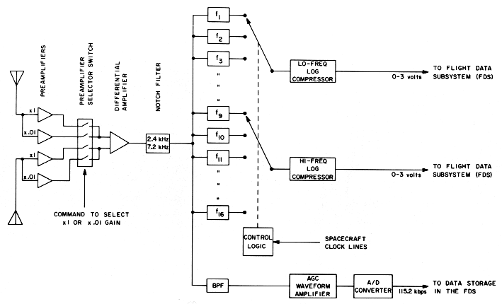
All of the signal processing for the plasma wave experiment is performed in a single main electronics box which is mounted near the electric antennas, above the PRA, as shown in Figure 6. The block diagram of the instrumentation in the main electronics box is shown in Figure 7. Signals from the electric antennas go to two pairs of preamplifiers; one pair is connected directly to the antennas (x1) and the second pair has a 40 db attenuator between the antennas and the preamplifiers (x0.01). The outputs of either pair of preamplifiers can be selected by command. This command permits us to shift the dynamic range of the experiment by 40 db if unusually large signals are detected during a planetary encounter. The selected preamplifier outputs then go to a differential amplifier which provides an output signal proportional to the voltage difference, hence electric field, between the antenna elements. A notch filter is used after the differential amplifier to attenuate interference signals at the spacecraft power supply frequency 2.4 kHz and its 3rd harmonic, 7.2 kHz.
Signals from the differential amplifier are processed in two ways: (1) by a 16-channel spectrum analyzer and (2) by a waveform amplifier. The 16-channel spectrum analyzer consists of 16 discrete filters with four frequencies per decade from 10 Hz to 56.2 kHz (i.e., 10 Hz, 17.8 Hz, 31.1 Hz, etc.). These filters have bandwidths of ±15.0% for the lowest 8 frequencies (active filters) and ±7.5% for the highest 8 frequencies (passive filters). The outputs from these filters are switched into two logarithmic detectors which provide output voltages (0 to 3 V) to the spacecraft data system. A reset pulse from the data system is used to synchronize the counter which controls the channel selection. The frequency selection and sampling rate of the spectrum analyzer outputs are completely controlled by programs in the flight data system. The normal operating mode assigned for planetary encounters involves one scan through all 16 frequencies in 4 sec (i.e., 32 bps).
The spectrum analyzer system gives high sensitivity but the threshold does vary somewhat with frequency. In terms of sine wave signals at the center frequencies of the bandpass channels, channel 1 (10 Hz) has a threshold of about 1.7 µ V m-1, while channel 16 (56 kHz) has a threshold of 0.3 µ V m-1.
The waveform amplifier and associated A/D converter shown in Figure 7 are intended to provide very high time resolution measurements of electric field waveforms at selected times during planetary encounters. A bandpass filter ahead of the waveform amplifier limits the bandwidth of these measurements to the range from 50 Hz to 10 kHz. The waveform amplifier consists of an automatic gain control circuit which maintains an essentially constant output amplitude independent of the amplitude of the input signal, with a time constant of 0.5 sec. The output of the waveform amplifier is sampled at a rate of 28 800 samples/second by a 4-bit A/D converter. The 115.2 kbps output from the A/D converter is recorded by the spacecraft data storage system at selected periods during planetary encounters.
The waveform channel provides an enormous increase in our ability
to identify and analyze wave phenomena because the broadband
measurement gives virtually continuous coverage in frequency and time,
subject only to the constraints of the
![]() f
f ![]() t
t
![]() 1 limitation. The data in the broadband panels of Figure 1 were all acquired using the waveform
capabilities of the IMP-6 and OGO-5 plasma wave instruments, together
with the high rate analog spacecraft telemetry links. For Voyager, the
128 kb/sec transmissions are digital, but the JPL Imaging Processing
Laboratory has existing data processing routines that can readily be
used to make up broadband frequency-time spectrograms similar to those
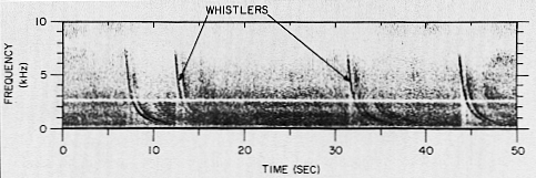
shown in Figure 1. For instance, we show in Figure 8 how an S3-A recording of a
lightning whistler would appear when the signal is played through the
Voyager PWS waveform link, and processed through the Imaging
Processing Laboratory facilities. Each flyby of Jupiter should provide
a total of more than 10 hours of such waveform data, and for JST we
anticipate that frequency-time spectrograms similar to Figure 8 will be available from the region of the
Io flux tube.
1 limitation. The data in the broadband panels of Figure 1 were all acquired using the waveform
capabilities of the IMP-6 and OGO-5 plasma wave instruments, together
with the high rate analog spacecraft telemetry links. For Voyager, the
128 kb/sec transmissions are digital, but the JPL Imaging Processing
Laboratory has existing data processing routines that can readily be
used to make up broadband frequency-time spectrograms similar to those
shown in Figure 1. For instance, we show in Figure 8 how an S3-A recording of a
lightning whistler would appear when the signal is played through the
Voyager PWS waveform link, and processed through the Imaging
Processing Laboratory facilities. Each flyby of Jupiter should provide
a total of more than 10 hours of such waveform data, and for JST we
anticipate that frequency-time spectrograms similar to Figure 8 will be available from the region of the
Io flux tube.
C. PHYSICAL CHARACTERISTICS
The packing of electronics in the main electronics housing consists of a combination of cordwood modules and custom hybrid circuits attached to a 0.062-inch printed circuit motherboard. The mechanical housing is machined from magnesium and is gold plated to provide a protective finish. Feed through filters on bulkheads and other filtering techniques are used to eliminate conducted RFI from the spacecraft. Physical and electrical characteristics of the instrument are summarized in Table 1.
D. PRIOR PERFORMANCE AND DESIGN HISTORY
The basic University of Iowa hybrid circuits and electronics designs used in this investigation have had extensive use in spacecraft plasma wave instrumentation over the past seven years, including flights on the IMP-6, S3-A, IMP-8, Hawkeye-1 and Helios-1,2 spacecrafts. Related plasma wave measurement techniques were used to fabricate instruments for Pioneer 8, 9, OGO-5, IMP-7, and similar hardware is now being integrated on the ISEE A, B, C and Pioneer-Venus-Orbiter spacecraft. The specific design of the Voyager Plasma Wave System bears a very close similarity to that of the S3-A plasma wave investigation, and the relatively minor changes that were imposed were primarily needed to: (a) accommodate the Voyager power supply and interface requirements, and (b) reduce susceptibility to radiation interference effects. The design, fabrication and testing of the Voyager PWS was performed by the staff of the University of Iowa.
E. RADIATION ENVIRONMENT EFFECTS
As part of the Voyager experiment development, extensive analysis and testing have been performed to assure that this subsystem will operate at Jupiter and survive the passage through the Jovian radiation belts. The proper operation and survival of the flight equipment in the Jovian radiation environment has been full confirmed by these analyses and tests. Specific steps that were taken to assure satisfactory operation include: (a) the exposure of samples of transistors from each wafer used to construct the flight unit hybrid circuits to suitable radiation levels, to verify that these specific transistor wafers are not defective or unusually sensitive to radiation; (b) the use of devices screened and tested by JPL for radiation resistance; (c) redesign of some circuits to make the operation more immune to radiation-induced parameter shifts.
G. SPACECRAFT CHARGING AND INPUT CIRCUIT PROTECTION
In a space plasma, photoelectron emission and secondary electron emission from the spacecraft surfaces are both generally significant, and plasma probe measurements always involve ambient distributions plus populations of charged particles that are emitted from or trapped near the spacecraft. At Jupiter, these complexities may also involve sputtering from spacecraft surfaces. Moreover, a plasma probe on a spacecraft always measures the spectrum of ions or electrons arriving at the detector, but these charged particles are locally accelerated or retarded by sheath fields. The energy shifts associated with the plasma sheath can be extremely important; DeForest (1972) showed that ATS-5 charged up to 10 kV (negative) when the electron temperature at synchronous Earth orbit (6.6RE) reached 10-20 kV during substorms, and the possible scientific relevance of this charging problem at Jupiter has been discussed by Scarf (1973, 1975) and by Mendis and Axford (1974). Higher spacecraft charging levels can generally be expected at Jupiter, and Pioneer 10, 11 measurements do indicate that large sheath field fluctuations did develop within about 13 RJ. For completely unconnected metal surfaces, potential differences of many kilovolts are likely at Jupiter, although the associated problems depend on the details of the spacecraft electrical and mechanical configuration. For Voyager wave experimenters, these considerations lead to special concerns about arcs and input circuit protection since the 10-m antennas must be floating with respect to spacecraft ground at all frequencies above 10 Hz.
Fortunately, Voyager is implementing an equipotential spacecraft design requirement so that there should be no possibility of arcs from thermal blankets, for instance, to the antennas. In this case, any change in antenna potential with respect to ground will be current limited to the maximum collection capability of the antenna, and we simply have to evaluate the maximum current that can be carried.
For E>10 keV, Pioneer 11 found J(max)
![]() 109 cm-2 sec-1 or
i(max)=1.6 x 10⁻¹⁰ A cm-2 (Fillius et al., 1975). We increase this
maximum by a factor of five to account for space, time variations,
E<10 keV electrons, Io emissions, etc. In this case, the
maximum charging current to the antenna (assuming no arcing) is
4µA, and a 20 M
109 cm-2 sec-1 or
i(max)=1.6 x 10⁻¹⁰ A cm-2 (Fillius et al., 1975). We increase this
maximum by a factor of five to account for space, time variations,
E<10 keV electrons, Io emissions, etc. In this case, the
maximum charging current to the antenna (assuming no arcing) is
4µA, and a 20 M![]() input resistor to
ground will keep the dc antenna-to-ground potential difference at or
below 80 V, which is well below the 500-V rating of this resistor and
the 500-V to 1 kV ratings of the PWS-PRA coupling capacitors. This
input resistor has been inserted to provide protection against the
development of extreme sheath field transients.
input resistor to
ground will keep the dc antenna-to-ground potential difference at or
below 80 V, which is well below the 500-V rating of this resistor and
the 500-V to 1 kV ratings of the PWS-PRA coupling capacitors. This
input resistor has been inserted to provide protection against the
development of extreme sheath field transients.
6. Concluding Remarks
The inherent noise detected in the plasma wave subsystem when mounted on the Voyager spacecraft and interconnected to the PRA front end and the antenna mechanisms appears to be far below the levels anticipated for ambient plasma waves at Jupiter or Saturn. In fact, the equivalent sine wave sensitivities of 1.7 µV/M (10 Hz) to 0.3 µV/M (56 kHz) are far below the ranges for signal levels customarily encountered in Earth orbit when discrete emissions or current-driven plasma waves are being studied. With reference to Figure 1, typical sine wave levels for 3fc-/2 emissions or ion acoustic waves at the bow shock range between 100 µ V/M and 10 mV/M [see, for instance, Kennel et al. ( 1970); Fredericks et al. (1970); Gurnett and Shaw (1973); Rodriguez and Gurnett (1975)], and even the high frequency fp- emissions (the weakest signals studied in Earth orbit) customarily have amplitude levels that are an order of magnitude above the PWS high frequency threshold.
Of course, these PWS sensitivities have not yet been measured in a plasma, and spacecraft noise coupling to the electric antenna through the plasma sheath can frequently produce serious problems that are only evident after launch. For Voyager, with its 2.4 kHz square wave power distribution, this kind of prospective spacecraft interference concerned us greatly during the design phase and led to the inclusion of the 2.4 kHz and 7.2 kHz notch filters. The use of a balanced dipole should also strongly reduce any in-orbit interference effects of this type since the balanced dipole gives a 40 db common-mode rejection that is very effective against spacecraft noises. Finally, the imposition of the Voyager electrostatic cleanliness specification should provide considerable additional protection since the thermal blankets and the mission Module structure form a relatively continuous Faraday shield that will keep much of the spacecraft noise away from the plasma. Since Voyager does not have solar arrays, which frequently provide strong coupling between spacecraft noise signals and the plasma, the prospects for a quiet environment around the Voyager spacecraft appear to be very good.
Acknowledgments
The plasma wave investigation was added to the Voyager payload at a late date, and the success of the PWS project is directly attributable to the exceptional support that has been provided by our colleagues at the University of Iowa, by so many members of the Voyager Project Staff at JPL and at NASA Headquarters, and by the Planetary Radio Astronomy team, led by James Warwick.
We are especially greatful to M. Agabra, the PWS Cognizant Engineer at JPL, and to R. Shaw, W. Kurth, S. Remington and R. Randall of the University of Iowa for their excellent and dedicated support and their many invaluable contributions throughout the design, fabrication, integration and launch preparation phases of this project.
TABLE I
Voyager plasma wave instrument
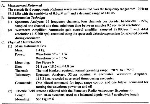
Fig. 1. Examples of plasma waves and wave-particle
interaction phenomena detected near earth. Broadband telemetry
observations from OGO-5 and IMP-6 were used to make up these
frequency-time diagrams. The arrows show typical locations in the
upstream region, at the bow shock, and in the near-equatorial region
of the magnetosphere. Examples of the important high-latitude
interactions and wave-particle interactions in the proton mode are not
shown, but these effects are summarized in the lower part of the
figure.
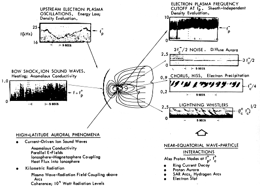
Fig. 2. The upper drawings show the JST and JSX (Uranus
option) flyby trajectories in relation to the anticipated extent of
the nominal Jupiter and Saturn magnetospheres. The lower panel
contains a partial listing of important outer planet wave-particle
interaction phenomena, with rough indications of the regions of
interest for the various observations.
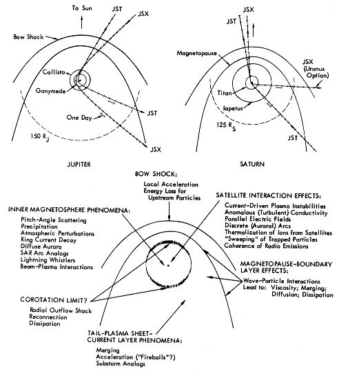
Fig. 3. Many of the recent models constructed to account for
the Io modulation of Jupiter’s decametric emissions invoke plasma
sheath effects and field-line coupling via current systems, as
sketched here. The labels indicate the many ways in which wave-
particle interactions and plasma instabilities are expected to affect
the microscopic processes along the field-lines threading the Io
sheath and ionosphere. Related processes should be important at other
satellites of Jupiter and Saturn.
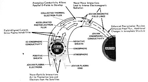
Fig. 4. If the physics of the Uranus plasma environment is
given by a model similar to that discussed by Siscoe (1975), then the magnetosphere of Uranus and the important wave-
particle interaction regions may be as shown (the sketch is adapted
from Siscoe’s paper).
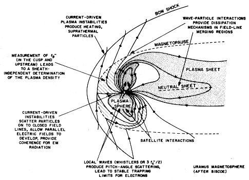
Fig. 5. The central panel shows how the characteristic
gyrofrequencies (fc±) and
plasma frequencies (fp±)
should vary with L-value at Jupiter. These gyrofrequency
profiles are derived from the Pioneer 10 data (Smith et al., 1974a,
b), and the plasma frequency profiles are
constructed from the theoretical model of Axford and Mendis
(1974). The Pioneer 10 plasma probe
measurements (Frank et
al., 1976) give somewhat higher plasma
frequencies within L![]() 6-7
(fp- up to about 70 kHz), but this
does not require any significant change in range for the Voyager
mission. The panel on the right contains a plausible scaled version
for Saturn, and the Voyager PWS frequency coverage (16-channel
spectrum analyzer plus broad wave-form channel) is roughly indicated
on the left (the lower eight channels actually have 30% bandpass
filters, with filter response curves that are broader than indicated
here).
6-7
(fp- up to about 70 kHz), but this
does not require any significant change in range for the Voyager
mission. The panel on the right contains a plausible scaled version
for Saturn, and the Voyager PWS frequency coverage (16-channel
spectrum analyzer plus broad wave-form channel) is roughly indicated
on the left (the lower eight channels actually have 30% bandpass
filters, with filter response curves that are broader than indicated
here).
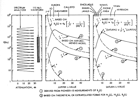
Fig. 6. The PWS, PRA electronic boxes and the extendible
antenna elements are mounted as shown on the left. The PWS uses the
orthogonal 10-m elements as a balanced Vee-type dipole, and the
effective length is about 7 m, as indicated.
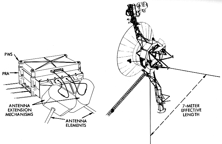
Fig. 8. A frequency-time spectrogram made up using an
S3-A lightning whistler recording as input for the Voyager
PWS broadband channel. The horizontal line is present because of the
action of the PWS notch filter.