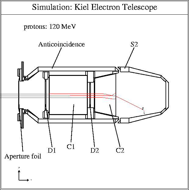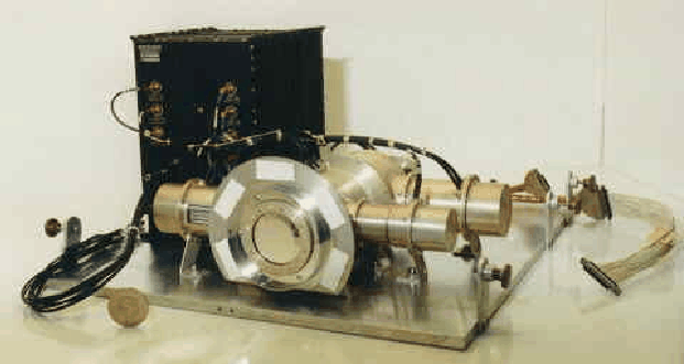
This figure displays in front the flight spare model sensor unit of the Ulysses Kiel Electron Telescope (KET) and in the back the electronics box. For comparison a five German mark coin is shown to demonstrate the size of the instrument. The KET is part of the Ulysses cosmic ray and solar particle investigation (COSPIN) experiment, which has been described in detail by Simpson et al. [4].
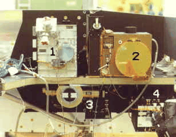
This figure shows the COSPIN sensor units as they are mounted on the spacecraft. The KET (3) is mounted below the Low Energy Telescope (LET), the Anisotropy Telescope (AT), the High Energy Telescope (HET) and the High Flux Telescope (HFT).
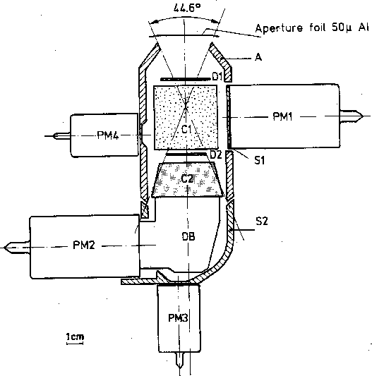
This figure shows a schematic sketch of the KET sensor system. D1 and D2 are 0.5 mm thick semiconductor detectors, C1 is an aerogel Cerenkov-detector and A a plastic anticoincidence scintillator. C2 is a lead fluoride Cerenkov-detector and S2 a plastic scintillator. PM1 through PM4 are photomultipliers.
Functionally, the detector system consists of two parts: an entrance telescope and a calorimeter, surrounded by a guard counter A.
- The entrance telescope
- is composed of a silica-aerogel Cerenkov detector C1 inserted between semi-conductor detectors, D1 and D2. Together with the guard counter A, this combination defines the geometry, selects particles with velocity beta>0.938 and determines the particle charge.
- The calorimeter
- consists of a 2.5 radiation length
lead-fluoride (PbF2) crystal used as Cerenkov detector (C2) and a
scintillator S2. In C2 an electromagnetic shower can develop. The number of
electrons leaving the PbF2-crystal are counted in S2.
The KET is designed to measure electron, proton and alpha particle fluxes in several energy windows ranging from a few MeV/n up to and above a few GeV/n. The values listed in the following table are based on mean energy losses and geometry of the instrument.
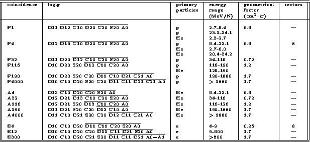
This table summarizes the KET coincidence channels. The coincidence name and trigger condition are displayed in the first two columns. The particles and their corresponding energy range are listed in columns three and four. The geometrical factor and sectorization information of the coincidence channels are in columns five and six.
Monte-Carlo-Simulation of the KET
A treatment of the response functions of particle telescopes, and a number
of exact formulae for multi-element telescopes have been given by
Sullivan, [5].
However, the determination of the response function of rather
complex telescopes like the KET instrument, makes a Monte Carlo
simulation mandatory. We assume that the differential coincidence counting
rate of a particle telescope can be expressed as:
where dCi,k is the differential coincidence counting rate in channel i,
Jk(E) the flux of particle species k with kinetic energy E, and
Rik(E) the response function for particle species k in channel i, to
be determined by the simulation. To get the counting rate Ci for the
channel i we have to integrate over E and sum up for all particle species.
In general, the response function may depend
on many variables like the angular distribution of the incident particle
flux, the location where a particle penetrates a detector etc.
Here we assume that R(E) is a function only of kinetic energy, valid for
particle fluxes which are almost isotropic over the effective opening
angle, and that the simulation properly averages over all other dependencies.
The Monte Carlo simulation was performed with the CERN Library Program
GEANT 3 (BRUN et al., [1]).
Particles were followed down to a low energy cutoff (electrons
and gamma-rays 50 keV, protons 300 keV), once reaching this
cutoff the particles were considered to be stopped and to have
deposited all of their kinetic energy in the traversed material.
The geometry of the detectors, mountings, foils, and the relevant structure
material as well as the energy resolution of the readout electronics were
accounted for in the simulation.
The model of the KET sensor unit in the simulation. Shown are three possible
tracks of 120 MeV protons. Two of these tracks are triggering the channel
P32 and on of them is counted in P116.
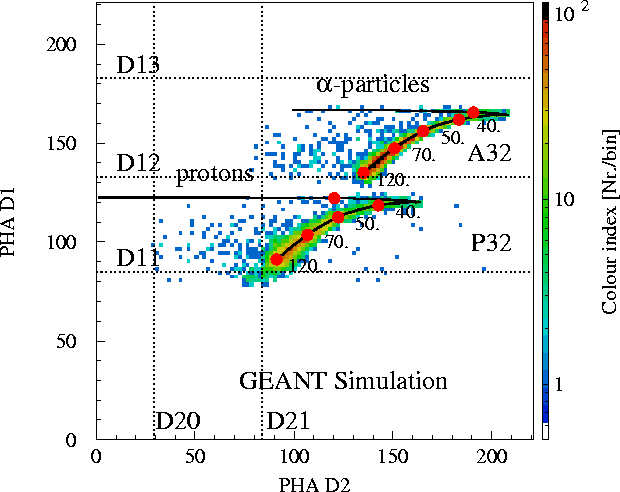
Calculated D1-D2 PHA-distribution (energy loss), using a proton and alpha
distribution which is a function of energy and isotropic in direction.
The solid lines show the mean energy losses. Marked on these lines are the
expected energy losses for 35, 40, 50, 70 and 120 MeV/n. The dotted
lines display the electronics thresholds. In comparison the following
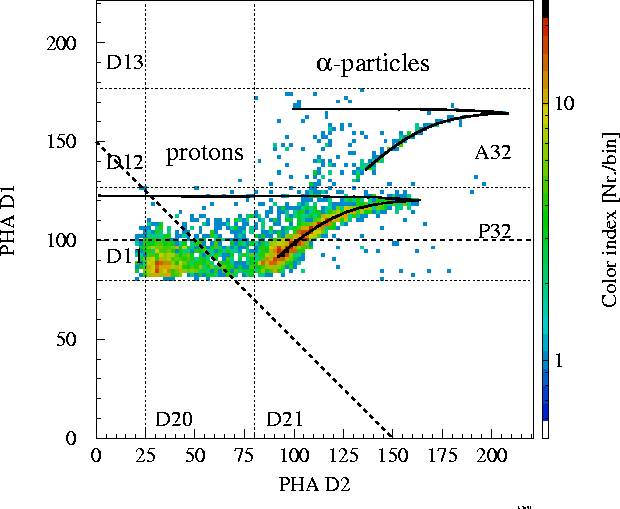
figure shows a PHA distribution measured in space:
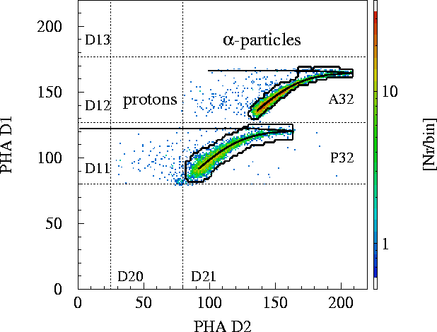
Measured P32-protons and A32-alpha-particle D1-D2 matrix in January 1991.
The entries below the dotted line could be identified as background random
coincidences (HEBER, [2]). As is discussed in detail in
HEBER, [2], the proton and alpha-tracks
in that matrix are well described by the Monte-Carlo simulation.
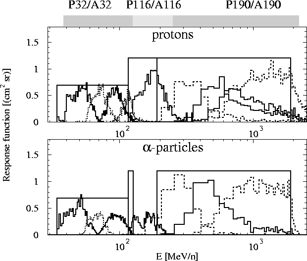
One important result of the analysis are the determination of the geometrical
factors as a function of energy:
Response functions RSimi(E) for isotropic
protons and alpha-particles. The rectangular boxes indicate the response
functions expected by using the Sullivan [5] theory.
For the low energy channels this theory is a good approximation.
KIEL ELECTRON TELESCOPE readme
This readme was last modified March 10, 1998
and shall explain the file structure of the KET files provided
for the Ulysses Data System (UDS). The previous sections "The Kiel Electron
Telescope Sensor System" and "Monte-Carlo-Simulation of the KET"
explain the instrument. Only count rates are provided for the UDS, because
the geometrical factors may change in future.
The geometrical factors provided in the
previous section should be checked against the values on our homepage:
All Ulysses data system files (UDS files) have the name
Herein YY is the year (eg. 90) and DOY the day of the year (eg. 365 of year
90 is 31.12.90).
The KET files are written on a VMS machine using Fortran 77 Routines. The
format used is:
Parameters are:
===============================================================
The daily averaged and 27 day averaged data are also provided.
See readme.daily 3.3 and readme.27days
3.4.
===============================================================
=================================================
Readme, KET90-96.DAILY
The daily averaged file KET90-96.DAILY contains a subset of KET coincidence
channels which can be corrected by using Pulse Height Analysis (see
Heber [2]). As an example the masks choosen for K3 and K34 are
shown in the following figure.
Definition of PHA masks in K3, K33 Matrix using the result of a GEANT
simulation.
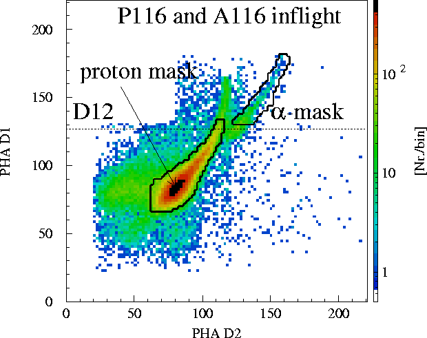
Definition of PHA masks in K34, K29 Matrix using the result of a GEANT
simulation. In contrast to the upper panel inflight data are shown. Note
that we used a for this figure a time period of 30 days. Because of the low
PHA-statistics for K29 no daily averaged corrected rates are given on a one
day basis.
The KET file was written on a VMS machine using Fortran 77 Routines. The
format used is:
Parameters are:
The KET files are written on a VMS machine using Fortran 77 Routines. The
format used is:
References
G/(cm2 sr MeV/n)
E /(MeV)/n
Sigma;E/(MeV)/n
protons K3 S 57.8 81.0 26.1 alpha-particles K33 S 52.7 78.2 24.0 protons K34 S 83.3 190 42 alpha-particles K29 S 23.4 164 25 protons K12 1 230 315 160 2 500 700 390 3 1370 1250 420 4 1500 950 490 alpha-particles K31 A 220 315 150 B 480 700 390 C 1320 1250 420 D 1500 950 490
      IMPLICIT REAL(K)
               WRITE(40,'(6I5)') IYEAR,IDOY,IHOUR,IMIN,ISEC,ICOV
               WRITE(40,'(10G11.3)')
     1             K1,K21,K22,K23,K24,K25,K26,K27,K28,P4
               WRITE(40,'(10G11.3)')
     1             K3,K34,K12,K10,K2,K33,K29,K31,K30,K13
               WRITE(40,'(10G11.3)')
     1             K14,K15,K16,K17,K18,K19,K20,E4,K11,K32
               WRITE(40,'(6G11.3)')
     1             D10,D20,C10,C20,A01
IYEAR: year IDOY: day of year IHOUR: hour IMIN: minute ISEC: second ICOV coverage in percent KET channel energy range A&A energy range Monte-Carlo simulation K1: protons (2.7-5.4 MeV) K21-K28: " (5.4-23.1 MeV) sectors 1 through 8 P4: " (5.4-23.1 MeV) omnidirectional K3: " (34.1-125.0 MeV) K34: " (125.0-320.0 MeV) (125.0-250.0 MeV) backward penetrating particles (160.0-260.0 MeV) K12: " (320.0-2100.0 MeV (250.0-2200.0 MeV) backward penetrating particles (260.0-2200.0 MeV) K10: " (>2100.0 MeV) (>2200.0 MeV) backward penetrating particles (>2200.0 MEV) K2: helium (6.0-20.4 MeV) K33: " (34.2-125.0 MeV) K29: " (125.0-320.0 MeV) (125.0-155.0 MeV) backward penetrating particles (155.0-225.0 MeV) K31: " (320.0-2100.0 MeV) (250.0-2100.0 MeV) backward penetrating particles (250.0-2100.0 MeV) K30: " (>2100.0 MeV) K13-K20: electrons (2.5-7.0 MeV) sectors 1 through 8 E4: " (2.5-7.0 MeV) omnidirectional K11: " (7.0-170.0 MeV) K32: " (>170.0 MeV) D10 - A01: single detector count rates
KET channel Gi K1 18 K21 - K28 120 P4 120 K3 70.0 K34 152.0 K12 3300.0 K10 na K2 120 K33 70.0 K29 88.0 K31 3200.0 K13-K20 na E4 na K11 na K32 na
GET LOW FLUX VALUES FROM THE PI ON LONGER ACCUMULATION PERIODS
===============================================================
Levels below 3.0e-3, 2.5e-3 should not be considered.
===============================================================
Caution: Very high fluxes for KET !!!!
=================================================
      IMPLICIT REAL(K)
	       WRITE(40,'(I2,1X,I3,1X,I3,1X,8G10.3/10X,6G10.3)')
     1         IYEAR,IDOY,ICOV
     1         K3,EK3,K34,EK34,K12,EK12,K10,EK10,
     1         K33,EK33,K31,EK34,K30,EK30
IYEAR: year IDOY: day of year ICOV coverage in percent KET channel energy range A&A energy range Monte-Carlo simulation K3: protons (34.1-125.0 MeV) EK3: error of preceeding value K34: " (125.0-320.0 MeV) (125.0-250.0 MeV) backward penetrating particles (160.0-260.0 MeV) EK34: error of preceeding value K12: " (320.0-2100.0 MeV (250.0-2200.0 MeV) backward penetrating particles (260.0-2200.0 MeV) EK12: error of preceeding value K10: " (>2100.0 MeV) (>2200.0 MeV) backward penetrating particles (>2200.0 MEV) EK10: error of preceeding value K33: helium " (34.2-125.0 MeV) EK33: error of preceeding value K31: " (320.0-2100.0 MeV) (250.0-2100.0 MeV) backward penetrating particles (250.0-2100.0 MeV) EK31: error of preceeding value K30: " (>2100.0 MeV) EK30: error of preceeding value
Readme, KET90-96.27DAYS
      IMPLICIT REAL(K)
               WRITE(40,'(4I3,2G13.4)') IYEAR,IDOY,IHOUR,IMIN,E4,EE4
Parameters are:
IYEAR: year IDOY: day of year IHOUR: hour IMIN: minute KET channel energy range A&A energy range Monte-Carlo simulation E4: " (2.5-7.0 MeV) omnidirectional EE4: error of preceeding value
