This document will serve to
provide users of the MESSENGER Energetic Particle and Plasma Spectrometer
(EPPS) data products with a detailed description of the EPPS instrument, data
product generation, validation and storage. Note that the EPPS is made up of two instrument
subsystems, the Fast Imaging Plasma Spectrometer (FIPS), and the Energetic
Particle Spectrometer (EPS). The
FIPS and EPS will be described in individual sections within this document.
They will be referred to separately when necessary and referred to as the EPPS
instrument when dealing with areas common to both instruments. The FIPS covers the lower energy range
of particles and measures the mass per charge (M/Q), energy per charge (E/Q)
and incoming direction of each charged particle. The EPS covers the higher
energy range and measures mass, energy, and incoming direction of each
particle. The MESSENGER EPPS data products are deliverables to the Planetary
Data System (PDS) and the scientific community that it supports. All data
formats are based on the PDS standard.
The EPPS science data are divided into two categories:
Level 2 edited-raw data (referred to as experiment data records or EDRs) and
processed data (referred to as reduced data records or RDRs). RDRs are
generated from EDRs, and represent data calibrated to a physical unit such as
particle intensity (Level 3), resampled Level 4 data products, or derived Level
5 data products. This SIS describes the EPPS EDR data products.
EDRs consist of unprocessed instrument-count data
including a description of the observation geometry (boresight, spacecraft, and
target). In those cases where on-board compression has been applied, the EDRs
will contain the decompressed version of the compressed instrument data as
downlinked to the SOC through the Deep Space Network (DSN). The
decompressed EDR data will be delivered to the PDS as CODMAC Level 2 data.
EPPS’s EDR is formatted to include standard PDS labels, spectra, pulse-height
analysis and housekeeping data (instrument count data are otherwise unprocessed).
To make full scientific utilization of the archived EDR data, processing such
as conversion of data values into engineering units, and geometric
rectification may be necessary. A detailed description of all data products in
the EPPS’s EDR follows.
In addition this SIS describes the
EPPS documentation volume, which will contain products related to both the EDR
and RDR level archives. The contents of the documentation volume will enable
one to conduct useful analysis of the EDRs. The documentation volume is
described in greater detail in section 6.6.
The MESSENGER EPPS SIS is
responsive to the following Documents:
·
Planetary Data System
Standards Reference, Aug 1, 2003, Version 3.6. JPL D-7669, Part-2.
· MESSENGER Data Management and Archiving Plan. The Johns
Hopkins University, APL. Document
ID number 7384-9019
·
MESSENGER Project
Archive Generation, Validation, and Distribution Plan
·
MESSENGER Mercury:
Surface, Space Environment, Geochemistry, Ranging; A mission to Orbit and
Explore the Planet Mercury, Concept Study, March 1999. Document ID
number FG632/ 99-0479
·
[PLR] Appendix 7 to
the discovery program Plan; Program Level Requirement for the MESSENGER
Discovery project; June 20, 2001.
This
document references several other documents as well:
·
Energetic Particle and
Plasma Spectrometer (EPPS) Instrument Flight Software Specification, version
3. Horace Malcom, The Johns Hopkins
University Applied Physics Laboratory document JHU/APL 7389-9041, November 12,
2003.
·
FIPS Data Processing
and Instrument Control, Steve Rogacki and Jim Raines, The University of
Michigan Space Physics Research Laboratory document 082-170, rev. G, January
21, 2003.
·
Livi et al. (The energetic particle spectrometer
(EPS) on MESSENGER: Instrument description, characterization, and calibration, MESSENGER
Project report, 2004.
·
Zurbuchen et al. (The Fast Ion Plasma
Spectrometer (FIPS) calibration report, MESSENGER Project report, 2004)
·
Energetic Particle and
Plasma Spectrometer (EPPS) Instrument Flight Software Specification, version
6. Horace Malcom/John Hayes, The
Johns Hopkins University Applied Physics Laboratory document JHU/APL 7389-9041,
rev B, July 12, 2008
This document has
undergone several revisions. The following are those revisions available from
the PDS:
·
MESSENGER Software Interface Specification for
the Energetic Particle and Plasma Spectrometer, Version 2F, 10/10/2006. First version delivered to PDS.
·
MESSENGER Software Interface Specification for
the Energetic Particle and Plasma Spectrometer, Version 2G, 12/10/2007. Second version delivered to PDS. This
version describes Version V1.0 of the EPS and FIPS datasets. Minor changes.
The EPPS EDR data products are stored on Hard Disk and in an
SQL (Structured Query Language) relational database for rapid mission access
during mission operations. The data products will be electronically transferred
to the PDS Planetary Plasma Interactions (PPI) Node according to the delivery
schedule in the MESSENGER Data Management and Archiving Plan. The data in the
EDR files themselves will be stored in a PDS binary TABLE object unless stated
otherwise (section 5.2).
Due to changes in the EPPS
flight software, several new EDR’s have been added, and several have been
retired. In addition, the formats of some of the EDR’s have been updated. Due
to these changes, the EPS and FIPS data sets have been advanced to version
V2.0. These versions supersede and replace version V1.0. The new data set identifiers are:
- MESS-E/V/H/SW-EPPS-2-EPS-RAWDATA-V2.0
- MESS-E/V/H/SW-EPPS-2-FIPS-RAWDATA-V2.0
The following table summarizes the changes from V1.0 to
V2.0. Also see tables 2 and 8, following for more details.
Table 1 Data Set Version Comparison
|
EDR
|
Data Set Version 1.0
|
Data Set Version 2.0
|
|
EPSHIGH
|
Exits
|
Retired, FSW6, 8/18/2008
|
|
EPSHI_HK
|
Exits
|
Retired, FSW5, 9/6/2007
|
|
EPSMED
|
Exits
|
Retired, FSW6, 8/18/2008
|
|
EPS_PHA
|
Exits
|
Changed, FSW6, 8/18/2008
|
|
EPS_HIRES
|
Not Included
|
New, FSW6, 8/18/2008
|
|
EPS_LORES
|
Not Included
|
New, FSW6, 8/18/2008
|
|
EPS_SUM
|
Not Included
|
New, FSW6, 8/18/2008
|
|
EPS_SCAN
|
Not Included
|
New, FSW6, 8/18/2008
|
|
FIPS_HI
|
Exits
|
Changed, FSW5, 9/6/2007
|
|
FIPS_HK
|
Exits
|
Retired, FSW5, 9/6/2007
|
|
FIPS_MED
|
Exits
|
Retired, FSW5, 9/6/2007
|
|
FIPS_PHA
|
Exits
|
Changed, FSW5, 9/6/2007
|
|
FIPS_SCAN
|
Not Included
|
New, FSW6, 8/18/2008
|
|
FIPS_HRPVD
|
Not Included
|
New, FSW6, 8/18/2008
|
|
EPPS_STATUS
|
Exits
|
Retired, FSW5, 9/6/2007
|
|
EPPS_LONG
|
Not Included
|
New, FSW5, 9/6/2007
|
The roles and responsibilities of the instrument teams,
Applied Physics Lab (APL), Applied Coherent Technology (ACT), and the Planetary
Data System (PDS) are defined in the MESSENGER
Data Management and Archiving Plan.
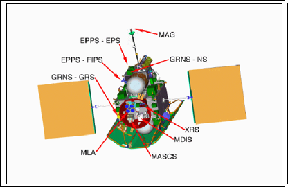
The EPPS system encompasses two
instrument subsystems – the Energetic Particle Spectrometer (EPS) and the
Fast Imaging Plasma Spectrometer (FIPS). EPS covers the energy range of 25 to
>500 keV for electrons, and 10 keV/nucleon to ~3 MeV total energy for
ions. FIPS covers the energy/charge
range of <50 eV/q to 20 keV/q.
The Johns Hopkins University/Applied Physics Laboratory constructed the
EPS instrument. It provides
electron, high and low-energy ion as well as diagnostic events as a single
stream of data that is placed into the EPS event FIFO for processing by the
EPPS flight software. The FIPS instrument was constructed by the University of
Michigan Space Physics Research Laboratory. It provides a single serial stream of
event data to the EPPS system at rates of up to 50K events/sec. The desired
throughput for FIPS charged particle event processing as well as for EPS event
processing is 5 kHz. FIPS generates a single 48-bit raw event packet format
which includes a 1-bit header that identifies the event as a proton event or a
non-proton event; an 11-bit TOF value; as well as a Wedge, Strip and ZigZag
values (each 12 bits in size). In addition, the FIPS system generates counter
and housekeeping information that the EPPS software can access via the I2C bus
interface. Detailed descriptions of
the EPS and FIPS sensor can be found, respectively, in Livi et al. (The
energetic particle spectrometer (EPS) on MESSENGER: Instrument description,
characterization, and calibration, MESSENGER Project report, 2004) and
Zurbuchen et al. (The Fast Ion Plasma Spectrometer (FIPS) calibration report, MESSENGER
Project report, 2004).
The Fast Imaging Plasma
Spectrometer (FIPS) sensor is designed to measure the distributions and
composition of magnetosphere ions as well as to characterize the nature of the
planetary magnetic field of Mercury.
It will do this by measuring the mass per charge, the energy per charge,
and incident angles for particles entering the
sensor. The particle
intensity is also calculated from the event rate
information.
The FIPS consists of an
electrostatic analyzer (ESA), located at the entrance to the sensor, a post
acceleration chamber between the output of the ESA and the carbon foil, and a
time-of-flight telescope. The ESA
at the entrance to the FIPS acts as a wide-angle lens for ions. It only allows
ions with a specific energy/charge band to enter through its output plane. This band is stepped through 64 values
to complete one measurement cycle (scan).
The times spent in each step can, in principal, be set to arbitrary
values, different for each step.
However, FIPS is normally operated in one of two stepping rates, once
step per second (normal mode) or one step per 100 milliseconds (burst
mode). When delays due to high
voltage ramp-ups are included, these result in cycle times of 64 sec and 8 sec,
respectively. Associated with each
step in a scan is a voltage setting, a threshold, a settling time, and a
duration or time interval after which the next voltage step is performed. Ions exit the output plane of the ESA
and are then accelerated in the post acceleration chamber. This acceleration is done to boost low
energy ions to penetrate the carbon foil. The acceleration also helps to
reduce energy straggling and angular scattering – effects that cause
degradation in mass resolution and imaging. The carbon foil serves as the source for
secondary electrons, which are scattered out by the penetration ions. After penetrating the foil, the particle
resides within the TOF (time-of-flight) chamber where velocity and incoming
angle are computed. Velocity is
determined by the time difference between the generation of secondary electrons
in the start foil and a stop surface, and angle is determined by spatially
imaging the position of the generation of the start secondary electrons. From the velocity, energy per charge,
and the post acceleration potential it is then possible to calculate the mass
per charge. The measured species
for the FIPS range from H to Fe.
The FIPS instrument provides a
single serial stream of event data to the EPPS system at rates of up to 50K
events/sec. The EPPS software maintains a mass distribution spectrum for the
FIPS instrument. This spectrum consists of a collection of two hundred
fifty-six bins (each 24 bits wide) that count the number of events
corresponding to M/Q values. In addition the software maintains a set of 5
element energy spectra. Each FIPS
spectrum corresponds to a specified M/Q range and consists of sixty-four 24-bit
bins. For events whose M/Q values
fall within one of the selected ranges, an energy value is computed and used to
determine which bin within the corresponding spectrum to increment. The spectra
are accumulated over an integral number of voltage scans, after which they are
compressed and output in telemetry. FIPS also records 5 heavy ion
energy-summed images (called “velocity distributions”) for each of the same 5
M/Q values plus one for protons.
A commanded number of raw events will be
recorded at each scan level.
The Energetic Particle
Spectrometer (EPS) determines the distributions of the higher energy
magnetospheric ion and electrons, including the composition of the ions to characterize
the nature of the planetary field of Mercury. It does this by measuring the energy and
velocity of the particles and then using a look-up table to determine the mass
and therefore the species of particle. The measured species for the EPS include
H, He, CNO, Fe, and electrons.
Electrons are measured by solid-state detectors behind absorbing
aluminum flashing.
The EPS sensor consists of a 60mm
diameter, tuna-can-like cylinder, in which a start foil and stop foil, wrapped
around opposite curved sides of the cylinder, constitute the time-of-flight
chamber. An incoming particle hits the start foil and scatters one or more electron,
which is attracted to the start anode ground. The particle continues and hits the stop
foil, scattering other electrons, which are then attracted to the stop
anode ground. The solid-state detectors outside of, but wrapped around the
curved face of, the stop foil, then detect the
particle and measure the energy state.
The detectors are arranged so that
each detector senses the events within a given range of incidence angles. Each of the six detector modules is
composed of four pixels: large and small ion and large and small electron. This
provides 24 detector elements. At
any one time, 12 of the 24 elements are used (6 ion and 6 electron
detectors). Each of the six EPS
detector modules also maintains its own spectrum via sixty-four 16-bit bins.
Sixty-three bins will count the particle/energy combinations of interest, and
one will count the remaining “background” events which do not fall in the
particle/energy combinations of interest. The spectra are accumulated over a
time set by ground command, after which they are compressed and reported in
telemetry.
The EPS system also includes
thirty-two 16-bit rate counters and three 24-bit rate counters that are read by
the EPPS software every n seconds (n specified by command). EPS status and
housekeeping data such as voltages, currents and temperatures are also
periodically sampled.
The EDR data products generated by the EPS and FIPS
subsystems, as well as the EPPS instrument status EDR, are described in this
section. For all the EDR products
there is a detached PDS label file which describes the contents of one data
file. Each label file will have the same base name as the data file it is
describing, with the extension “.LBL” to denote a label file. The label file
defines the start time and end of the observation, product creation time, and
the structure of the binary (or ASCII) tables.
The data product overview will first cover the EDRs unique
to the EPS and FIPS subsystems, then describe the EPPS Engineering and Status
EDR. There are a total of 9 EDR data products. Four of these are science and
ancillary data products for the EPS instrument. Four others are science and
ancillary data products for the FIPS instrument. The last is the engineering
and status data products for the entire EPPS instrument. Each data file
contains the data collected on a given earth day.
The EPS portion of the data archive
currently consists of five EDR data products. The EPS instrument creates all of
its different science data packets during one observation, but the packets are
telemetered to the ground at different times. The different formats of these data
packets do not lend themselves to standardization into one EDR file format.
Therefore, different EDR formats have been developed, each of which captures
one specific data grouping such as spectra or PHA data. A given EDR data file
will contain all the observations obtained on same earth day. The following table shows the
different EPS data products. Each data product is identified within the PDS
label by a STANDARD_DATA_PRODUCT_ID value (shown in parentheses).
The table has been updated to reflect an instrument
flight software (FSW) version 6 upload on 8/18/2008, henceforth known as the
FSW6 upload. The software changed to consolidate and improve instrument
telemetry allocation on EPS. During
the time of instrument check out shortly after launch, EPS’s time-of-flight
section suffered a failure, subsequently, EPS lost its ability to measure ions
by elemental mass species (can only now measure ion and electron). Hence a change of FSW is required to
improve EPS’s ion and electron data products. This software upload changed the
packet formatting such that two EPS EDRs had to be retired and be replaced by
two new EDRs. Two additional EDRs had to be created to store data from two new
instrument packets. Finally, the format for the EPS PHA EDR has been updated to
be support slight changes in the PHA data. The new PHA data format will be
consistent for EDRs before and after the flight software upload. The new flight
software code was uploaded on 8/18/2008 and implemented on 8/19/2008. Thus,
data on or after 8/19/2008 is generated from FSW6.
In addition, version 5 of the instrument
flight software (FSW5), uploaded 9/6/2007, consolidated the EPS housekeeping
data with FIPS housekeeping data in a new EDR, the EPPS_LONG. Thus the High
Priority Housekeeping (EPS_HI_HOUSEKEEPING) EDR has also been retired.
Version 7 of the instrument flight
software (FSW7), uploaded on 8/18/2009, did not affect the format of the EPS
EDRs. Thus, data on or after 8/18/2009 is of the same format as data generated
from the FSW6 upload. FSW7 does affect the FIPS EDRs and changes are detailed
in section 5.2.2.
Table 2 EPS Data Products
|
Current Data Products
|
|
Data
Product
|
Product
Description
|
|
|
· PDS label file
– describes data product and contains pointers to the data file:
·
PHA Data – contains Pulse Height Analysis data in
binary table format. The PHA data product is generated from the high, medium,
or low priority science packet. The priority level will be identified within
the PDS label.
· As of
8/18/2008 the PHA data product is generated from PHA data packets. There is
no priority level associated with the PHA EDR since the high, medium, and low
priority packets are retired on 8/18/2008.
|
|
|
· PDS label file
– describes the data product and contains pointers to the data file:
·
Data file – high-res (energy channels) ion and
electron energy spectra
|
|
|
· PDS label file
– describes the data product and contains pointers to the data file:
·
Data file – lo-res (energy channels) ion and
electron energy spectra and rate counters.
|
|
|
· PDS label file
– describes the data product and contains pointers to the data file:
·
Data file – Contains a subset of rate counters and
low resolution energy spectra
|
|
|
· PDS label file
– describes the data product and contains pointers to the data file:
·
Data file – Contains the integrated hardware
counters over four energy thresholds. Each threshold setting and integration
lasts ¼ second.
|
|
Retired Data Products
|
|
Data
Product
|
Product
Description
|
|
|
· PDS label file
– describes the data product and contains pointers to the data file:
·
Spectra Data – contains spectral data, hardware and
software rate counters in binary table format. Data and counter values are
taken from the High Priority (order that they download to ground) Science
Packet
|
|
|
· PDS label file
– describes the data product and contains pointers to the data file:
·
Housekeeping ASCII table file – contains 33 fields
of housekeeping data.
|
|
|
· PDS label file
– describes data product and contains pointers to the data file:
·
Spectra data – contains spectral data, hardware and
software rate counters in binary table format. Data and counter values are
taken from the Medium Priority (order that they download to ground) Science
Packet.
|
The EPS Spectra Data is stored as
counts/accumulation for a number of defined data channels. The spectra are reported within 4
different classes of channels: high-resolution/low-resolution electron
channels, and high-resolution/low-resolution ion channels. The channels are defined in Tables
2-5. The information
provided in these tables is given for each of 6 different view directions. Note that the exact boundaries given
with either energies or times-of-flight are subject to change via ground
commands. Tables 2-5 list electron
energy levels as recorded within the onboard sensors and electronics. The translations of those electronic
levels to the energies of the incoming particles can be found in the Livi et
al. (2004) Calibration report referenced at the beginning of this document.
Table 3 EPS Low-resolution Electron Channels (Based on
Energy)
|
Channel
|
E1 (electronic)
|
E2(electronic)
|
Comments
|
|
|
keV
|
keV
|
|
|
0
|
0
|
21
|
Below Discrimination
|
|
1
|
21
|
28
|
Below Discrimination
|
|
2
|
28
|
35
|
|
|
3
|
35
|
56
|
|
|
4
|
56
|
71
|
|
|
5
|
71
|
112
|
|
|
6
|
112
|
141
|
|
|
7
|
141
|
224
|
|
|
8
|
224
|
447
|
|
|
9
|
447
|
708
|
|
|
10
|
708
|
1000
|
|
|
11
|
|
|
Overflow Channel
|
Table 4 EPS Low-resolution Ion Channels (Based on Energy)
|
Channel
|
E1 (electronic)
|
E2(electronic)
|
Comments
|
|
|
keV
|
keV
|
|
|
0
|
0
|
20
|
Below Discrimination
|
|
1
|
21
|
27
|
Below Discrimination
|
|
2
|
30
|
36
|
|
|
3
|
43
|
57
|
|
|
4
|
62
|
89
|
|
|
5
|
88
|
140
|
|
|
6
|
125
|
343
|
|
|
7
|
177
|
537
|
|
|
8
|
252
|
841
|
|
|
9
|
357
|
2065
|
|
|
10
|
507
|
2750
|
|
|
11
|
|
|
Overflow Channel
|
Table 5 EPS High-resolution Electron Channels (Based on
Energy)
|
Channel
|
E1 (electronic)
|
E2(electronic)
|
Comments
|
|
|
keV
|
keV
|
|
|
0
|
0
|
18
|
Below Discrimination
|
|
1
|
18
|
20
|
Below Discrimination
|
|
2
|
20
|
25
|
Below Discrimination
|
|
3
|
25
|
28
|
Below Discrimination
|
|
4
|
28
|
32
|
|
|
5
|
32
|
35
|
|
|
6
|
35
|
40
|
|
|
7
|
40
|
45
|
|
|
8
|
45
|
50
|
|
|
9
|
50
|
56
|
|
|
10
|
56
|
63
|
|
|
11
|
63
|
71
|
|
|
12
|
71
|
79
|
|
|
13
|
79
|
89
|
|
|
14
|
89
|
100
|
|
|
15
|
100
|
112
|
|
|
16
|
112
|
126
|
|
|
17
|
126
|
141
|
|
|
18
|
141
|
158
|
|
|
19
|
158
|
178
|
|
|
20
|
178
|
200
|
|
|
21
|
200
|
224
|
|
|
22
|
224
|
251
|
|
|
23
|
251
|
282
|
|
|
24
|
282
|
316
|
|
|
25
|
316
|
355
|
|
|
26
|
355
|
398
|
|
|
27
|
398
|
447
|
|
|
28
|
447
|
501
|
|
|
29
|
501
|
562
|
|
|
30
|
562
|
631
|
|
|
31
|
631
|
708
|
|
|
32
|
708
|
794
|
|
|
33
|
794
|
891
|
|
|
34
|
891
|
1000
|
|
|
35
|
|
|
Overflow Channel
|
Table 6 EPS High-resolution Ion Channels (Based on Energy)
|
Channel
|
E1 (electronic)
|
E2(electronic)
|
Comments
|
|
|
keV
|
keV
|
|
|
0
|
0
|
17
|
Below Discrimination
|
|
1
|
17
|
20
|
Below Discrimination
|
|
2
|
20
|
23
|
Below Discrimination
|
|
3
|
23
|
27
|
Below Discrimination
|
|
4
|
27
|
31
|
|
|
5
|
31
|
36
|
|
|
6
|
36
|
42
|
|
|
7
|
42
|
49
|
|
|
8
|
49
|
57
|
|
|
9
|
57
|
66
|
|
|
10
|
66
|
77
|
|
|
11
|
77
|
89
|
|
|
12
|
89
|
104
|
|
|
13
|
104
|
120
|
|
|
14
|
120
|
140
|
|
|
15
|
140
|
162
|
|
|
16
|
162
|
188
|
|
|
17
|
188
|
219
|
|
|
18
|
219
|
254
|
|
|
19
|
254
|
295
|
|
|
20
|
295
|
343
|
|
|
21
|
343
|
398
|
|
|
22
|
398
|
462
|
|
|
23
|
462
|
537
|
|
|
24
|
537
|
624
|
|
|
25
|
624
|
724
|
|
|
26
|
724
|
841
|
|
|
27
|
841
|
977
|
|
|
28
|
977
|
1135
|
|
|
29
|
1135
|
1318
|
|
|
30
|
1318
|
1531
|
|
|
31
|
1531
|
1778
|
|
|
32
|
1778
|
2065
|
|
|
33
|
2065
|
2399
|
|
|
34
|
2399
|
2750
|
|
|
35
|
|
|
Overflow Channel
|
The
element that is not represented in Tables 2-5 is directionality. The nominal total field-of-view (FOV) of
EPS is 160° x 12°. Because the
electron and ion Solid State Detectors (SSDs) are side-by-side, the total
electron or high energy ion FOV in the long dimension is about 1/12 smaller
(~13° smaller) or about 147°. And, the centers of the ion and electron
FOV’s are shifted with respect to each other by ~13°. Let us define two angles within the MESSENGER
spacecraft coordinate system:
“alpha” is the angle from the +Y(s/c) axis and within the Y(s/c)-Z(s/c)
plane (with “plus” angles viewing towards the +Z(s/c) axis); “beta” is the
angle for rotations away from the Y(s/c)-Z(s/c) plane. With these definitions, the total FOV of
EPS is roughly: (-80° <
alpha < +80°) and (-6° < beta < +6°). The ion FOV is (-67° <
alpha < +80°) and (-6° < beta < +6°). The electron FOV is (-80° <
alpha < +67°) and (-6° < beta < +6°). For low energy ions (where
the directionality is determined by microchannel plate anodes and not solid
state detectors), the field-of-view is :
(-80° < alpha < +80°) and (-6° <
beta < +6°).
The
direction within the ~160 degree field of view is determined for high-energy
ions and for electrons with the determination of which solid state detector
(SSD) was active. With the
high-energy ion and electron segments, there are a total of 12 SSD elements
active at any one time. The
numbering scheme for these detector elements ranges between 0 and 11, with the
even SSD elements corresponding to electrons and the odd SSD elements
corresponding to ions. The “0”
detector (an electron detector) is the one that looks most closely aligned with
the –Z(s/c) axis, while the “11” detector looks most closely to the
+Z(s/c) axis. In the data that is
telemetered to the ground, the directionality of the electrons and ions is
represented with a number between 0 and 5.
For electrons the directions (0, 1, 2, 3, 4, 5) correspond to SSD’s (0,
2, 4, 6, 8, 10). For high-energy
ions the directions (0, 1, 2, 3, 4, 5) correspond to SSD’s (1, 3, 5, 7, 9, 11).
There is a confusing element in
the representation of the directionality of low energy ions (time-of-flight
only). The directionality is now
determined not with the SSD’s but with the microchannel plate anodes. The numbering of the TOF Start-Anodes
ranges between 0 and 5. An ion or
electron that passes right over Start-Anode “0” (only the ion “stimulates” this
start anode) strikes either SSD 10 or SSD 11. Thus, the Start-Anodes 5, 4, 3, 2, 1,
and 0 map to SSD’s (0, 1), (2, 3), (4, 5), (6, 7), (8, 9), and (10, 11),
respectively. The confusing element
is that the Low Energy Ion direction “5” (representing the firing of anode “5”)
corresponds roughly (not exactly) to the High Energy Ion direction “0”, and the
Low Energy Ion direction “0” corresponds to the High Energy Ion direction
“5”. This confusing element
exists for historical reasons, and because this representation is how the
directionalities are indicated on board the instrument, we believed that even
more confusion would be introduced if we made a change within the data
generated on the ground.
In FSW6, the high (energy)
resolution spectral EDR product (EPS_HIRES_SPECTRA) is integrated for T*N1
seconds, where both T and N1 are commandable parameters. The EPS_HIRES_SPECTRA
data are sent from the spacecraft in high priority telemetry packets. The low (energy) resolution spectral EDR
product (EPS_LORES_SPECTRA) is integrated for T seconds (high time resolution)
and contains rate data as well as the low energy spectra. The EPS_LORES_SPECTRA
data are sent from the spacecraft in medium priority telemetry packets. The
EPS_SUMMARY_SPECTRA EDR product contains both high and low energy spectra and
is integrated over T*N1 (low time resolution). The EPS_SUMMARY_SPECTRA data are
sent from the spacecraft in high priority telemetry packets. It provides
redundant data and a quick look capability; it may be enabled or disabled by
command.
In previous releases, these
spectral products were identified by the priority with which the data packets
were telemetered by the spacecraft to the ground. In FSW6, this naming
convention has been discontinued.
The following table clarifies the relationship between the EDR names and
the various resolutions and priorities of the three principle products:
|
Product
|
Energy
Resolution
|
Time
Resolution
(Integration
Time)
|
Telemetry
Priority
|
|
EPS_HIRES_SPECTRA
|
High (36 bins)
|
T*N1 (low)
|
High
|
|
EPS_LORES_SPECTRA
|
Low (12 bins)
|
T (high)
|
Medium
|
|
EPS_SUMMARY_SPECTRA
|
Both
|
T*N1 (low)
|
High
|
New in the FSW6 is the Scan
data. In scan mode, EPS varies the
energy thresholds integrating hardware rates at each threshold setting (defined
in tables). The thresholds are changed
three times, then the base thresholds are restored. A scan is defined as four threshold
settings, three offsets and one nominal.
AT each threshold step, a subset of the hardware rate counters are
accumulated for ¼ second.
The Scan mode gives EPS the ability to lower its electronics threshold
by temporary suspending the processor operation.
5.2.1.1 Pulse
Height Analysis (PHA) Event Data
PHA events are stored by the EPPS flight software in either
the EPS High, Medium, or Low priority Science packet, for data prior to FSW6.
The following explains how PHA event data is collected for data prior to the
FSW6 upload on 8/18/2008. PHA events are distributed among the packet buffers
in round-robin fashion: the first detected event is stored into the
high-priority packet buffer, the next event is stored in the medium-priority
packet buffer, and the last event is stored into the low-priority packet
buffer. Please note that there is no individual time tag per PHA event.
Each event allocated to a particular buffer is simply stored
into the next slot within the buffer until the buffer fills up. Thereafter, a
rotating priority PHA replacement scheme is used in deciding which events may
be displaced from the filled buffer. The maximum number of PHA events saved per
integration period for a particular packet is shown in the following table:
Table 7 Maximum PHA Events per Integration
|
EPS Packet Type
|
Maximum number of PHA events
saved during each accumulation interval
|
|
High Priority
|
10
|
|
Medium Priority
|
20
|
|
Low Priority
|
300
|
Note that a given EPS science packet (which may or may not contain
PHA events) is time tagged with one MET time (not per PHA event). PHA events
are accumulated within an integration period depending on the priority of the
given science packet. Each PHA event is time tagged with the same MET
associated with the science packet in which it was contained. Thus, there will
be a maximum of 10 High Priority events with the same MET, 20 Medium Priority
events with the same MET or 300 Low Priority events with the same MET. A given
PHA EDR data file will contain the observations obtained on the same earth day
and arranged in time order. Therefore a given PHA EDR data file will contain a
set of N PHA events with the same MET, followed by another set of PHA events
with the same MET, etc.
The FSW6 upload created a PHA packet for the express purpose
of downloading PHA events. The EPS collects data for T*N1 seconds (where
T=integration time and N1 is the integration time multiplier). If the
integration is aborted then N1 will be the actual value instead of the
commanded value. Over the T*N1 integration time, EPS saves PHA data in the
order that it is seen. Each PHA packet can record a maximum of 934 PHA events.
The events in a single PHA packet are time tagged with one MET time.
FSW6 also retired the high, medium, and low priority packets
and consequently the capture of PHA events within those packets. The only
packet which contains EPS PHA events is the EPS PHA packet and is sent down as
a medium priority packet; the file naming convention will reflect that FSW6 PHA
EDRs are no longer associated with a priority level.
The FIPS portion of the data
archive currently consists of four EDR data products. As with the EPS the data collected in
one observation is downloaded at different times and in different packet
formats. Therefore, different EDR formats have been developed, each of which
presents a different grouping of the data. The following table shows the
different FIPS data products and their files. Each data product is identified
within the PDS label by a STANDARD_DATA_PRODUCT_ID value (shown in
parentheses). Note: a FIPS Flight Software Upload (FSW5) was conducted on Sept
6, 2007 which implemented several changes to the FIPS science packets. This in
turn changed the format of the FIPS EDRs. The EDRs prior to FSW5 were
regenerated to reflect the updated format. The FSW5 upload also modified the
FIPS High Priority Science packet: housekeeping data was no longer being stored
in the FIPS High Priority Science Packet. Instead, that housekeeping data was
added to the EPPS Status packet, which in turn led to the creation of the
EPPS_LONG_STATUS EDR. The FIPS_HI_HOUSEKEEPING EDR is no longer generated for
data collected on or after 9/6/2007.
This was superceded by a FIPS
Flight Software Upload (FSW6) conducted on 8/18/2008, henceforth known as the
FSW6 upload. This software upload changed the packet formatting such that the
Medium Priority FIPS Spectra EDR had to be retired and was replaced by FIPS
High Resolution Proton Velocity Distribution EDR. The FIPS SCAN EDR was created
to store data from a new instrument packet. The new flight software code was
uploaded on 8/18/2008 and implemented on 8/19/2008. Thus, data on and after
8/19/2008 is from the FSW6 load.
Another instrument flight software
upload (FSW7) was conducted on 8/18/2009. This software upload enable the
creation of Proton PHA events in addition to the existing Heavy Ion PHA events.
Both types of PHAs are combined in a single EDR file. The PHA data are also
exclusively generated by specific PHA packets. The naming convention for FSW7
PHA EDRs has been updated to reflect this change. Additionally the FIPS High Resolution
Proton Velocity Distribution EDR has been retired due to the FSW7 update.
The table below reflects the
changes brought about by each successive FSW upload.
Specific changes to the FIPS EDR
formats are described in a NOTE at the start of each FIPS format file.
Table 8 FIPS EDR Data Products
|
Current Data Products
|
|
Data Product
|
Product Description
|
|
|
· PDS label file
– describes data product and contains pointers to the data file:
·
PHA Data – contains FIPS Pulse Height Analysis data
in binary table format. This data
product is generated from either high, medium, or low priority FIPS packets.
The priority level will be identified within the PDS label
·
As of 8/18/2008 the PHA data product is generated from
High or Low Priority spectra packets or from FIPS Scan packets. The file naming convention will
identify the source packet.
|
|
|
· PDS label file
– describes data product and contains pointers to the data file:
·
Data file – contains rate counts sampled at each
Deflection System High Voltage (DSHV) step in a FIPS scan.
|
|
Retired Data Products (shown in retired time order)
|
|
Data Product
|
Product Description
|
|
|
· PDS label file
– describes the data product and contains pointers to the data file:
·
Housekeeping ASCII table file – contains 33 fields
of housekeeping data (contained in the high priority science packet).
|
|
|
· PDS label file
– describes data product and contains pointers to the data file:
·
Spectra Data file – contains proton velocity
distribution, hardware and software rate counters in binary table format.
Data and counter values are taken from the Medium Priority Science Packet
|
|
|
· PDS label file
– describes the data product and contains pointers to the data file:
·
Spectra Data file – contains spectral and velocity
distribution, hardware and software rate counters in binary table format.
Data and counter values are taken from the High Priority Science Packet
|
|
|
· PDS label file
– describes data product and contains pointers to the data file:
·
Data file – Contains a 32 x 32 high resolution
proton velocity distribution, integrated over a 10 scan sequence.
|
Each of these items is explained
in detail in the following sections.
Much of this information is updated from ‘FIPS Data Processing and
Instrument Control’. Further
details can be found in ‘EPPS Instrument Flight Software Specification’. (See
Section 2 of this document for full bibliographic information.)
5.2.2.1 Rate
Counters
Table 9 Rate Counters

The rate counters are 32 bit
values, which are compressed to 10 bits.
The first 3 rate counters listed are retrieved from FIPS at the end of
each energy/charge (E/q) step (typically 1 second per step). The Stop Events
counter is retrieved periodically and included in the housekeeping data. The fifth, Events Processed, counter is
internal to the EPS processor which, when compared with the Valid Event
counter, shows how many events have been registered in hardware but not
processed in software, due to time limitations. The rate counters are compressed using a
10 bit logarithmic compression code, 5 bits for mantissa and 5 bits for
exponent (5/5 compression).
5.2.2.2 Mass
Distribution and Element Energy Spectra
The Mass Distribution is a histogram of events classified by their
Mass/charge (M/q). All events are included in this data, both
proton and non-proton. The
Mass Distribution data object consists of 128 bins of 24 bit counters
(compressed to 10 bits using the 5/5 compression. Nominally, these 128 bins span 0.9 AMU
to 42 AMU, in a log scale. Bin 0
contains the sum of all events with M/q below the usable range (nominally 0.9
AMU) while bin 127 contains the sum of all events with M/q above the usable
range (nominally 42 AMU). This data
product is accumulated over a full scan sequence (10 scans; taking typically
~670 s in nominal mode).
To find the bin to increment, the
EPPS Flight software uses a lookup table based on the E/q step and the measured
TOF value. This lookup table is generated
in two parts: First, a table of M/q (in AMU/e) as a function of
E/q step and TOF is calculated:
M/q = 2 (kU + |Va|) * TOF 2 / ( d2 * 1040 ns2
keV / cm2 AMU)
where:
k
= deflection system constant, approx 1.33
U=
deflection system voltage, in kV
Va=
post acceleration voltage, in kV
TOF
= the measured Time of Flight, in ns
d
= distance over which TOF is measured, in cm.
Note: This equation does not include a term
for the carbon foil scattering and energy loss, which tends to spread the calculated
M/q values for each species making in flight calculations less precise than is
possible on the ground.
Second, the M/q values are binned
logarithmically across the M/q range (nominally 0.9-42 AMU/e):
Mq_bin = ( log(M/q) –
log(0.9) ) / ( (log(42) – log(0.9))/128 )
The Element Energy Spectra
represent the distribution of events over E/q that fall within a specified M/q
range. There are 5 separate
vectors, each corresponding to a different (commandable) M/q range, called
Energy Vector Ranges. These are
presented as histograms of 64 bins, each a 24 bit counter, compressed to 10
bits using 5/5 compression.
For inclusion in a data packet, the bins for each vector are ordered in
ascending order, 0-63, and the 5 vectors are ordered 1 through 5. This data product is accumulated over a
full scan sequence (10 scans; typically 670 s in nominal mode).
Figure 1 Graphical
depiction of relation among Element Energy Spectra, the Mass Distribution and
the E/q - M/q measurement space.
Note: Not all E/q or M/q bins are depicted.
5.2.2.3 PHA
Event Data
PHA words contain the
full-capability measurements of single particle events. Each PHA word contains
the TOF, E/q step, and (X, Y) location of the event on the start MCP. is accompanied
by its associated DSHV step number, a 6-bit value. The LSB of the TOF value is dropped, 11
to 10 bit. The X and Y positions
are calculated from the 12 bit Wedge, Strip, and Zigzag data. First commanded offsets are
subtracted from each value then the calculation below is performed:
The 28 bit packet is represented
as follows in the following order:
DS
voltage step [6
bits]
TOF [10
bits]
X = INT(128*Wedge/(Wedge+Strip+ZigZag)) [6
bits]
Y= INT(128*Strip/(Wedge+Strip+ZigZag)) [6
bits]
Since not all PHA words can be
telemetered to the ground, a representative sample is transmitted according to
a buffered, rotating priority scheme.
As events are collected, the flight software stores up to 12 events per
deflection system voltage step in a buffer. At the end of the scan, these events are
read out in voltage step order, one from each voltage step. Within a voltage step, PHAs are read out
in the same order that they were stored.
When no PHA exists for a given voltage step, one is read from the next
voltage step which has PHAs remaining, until the allowed number of PHAs (quota)
for this scan have been selected.
The quota is 128 PHAs per scan for High and Medium priority events. The quota for Low priority events is set
by ground command, with a maximum of 617 PHA words. This scheme has the effect of
downlinking a selection of PHAs which are as evenly distributed across voltage
steps as possible, while still telemetering the full quota of PHA words.
High or Medium priority PHA events
contain the DS voltage step, TOF, X, and Y values. Low priority PHA events
contain the DS voltage step, Wedge, Strip, and ZigZag values. Proton PHA words
are not included and thus never included in the data. The ‘Valid Event’ rate is then
used to calculate the appropriate weight of each transmitted PHA word which
would reconstruct the distribution of actual valid events.
The PHA events are included as
part of the FIPS high, medium, or low science packets. As of FSW6 PHA events
are also included as part of the FIPS Scan packet. There is only one MET time
tag associated with a science packet, even though it may contain multiple PHA
events. Thus, the FIPS PHA EDRs will contain multiple records with the same MET
timestamp. The maximum number of PHA events with the same MET timestamp is
dependent on the priority level of the PHA event. It is possible to narrow the MET time
window associated with a set of PHA events by combination of the E/q step
number with the stepping rate. See
section 5.1.1 for a description of FIPS stepping rate and note that MET timestamps
are for the end of the scan. This
priority level is assigned based on the priority of the telemetered science
packet containing the PHA event. The maximum number of PHA events
contained for a particular packet type is shown in the following table:
Table 10
Maximum PHA Events per Packet Type
|
FIPS Packet Type
|
Maximum number of PHA events
contained in the packet
|
|
High Priority
|
64
|
|
Medium Priority or FIPS Scan
|
128
|
|
Low Priority
|
617
|
|
Heavy Ion (FSW7)
|
617
|
|
Proton (FSW7)
|
1169
|
Note that a given FIPS science packet (which may or may not
contain PHA events) is time tagged with one MET time. PHA events are
accumulated within an integration period depending on the priority of the given
science packet. Each PHA event is time tagged with the same MET associated with
the science packet in which it was contained. Thus, there will be a maximum of
64 High Priority events with the same MET, 128 Medium Priority events with the
same MET or 617 Low Priority events with the same MET. A given PHA EDR data
file will contain the observations obtained on the same earth day and arranged
in time order. Therefore a given PHA EDR data file will contain a set of N PHA
events with the same MET, followed by another set of PHA events with the same
MET, etc.
EDR priority designations have been eliminated with the introduction of FSW7.
Now there are just 2 types of PHA packets – heavy ion and proton.
However, the descriptions given above with regard to the MET time tags and EDR
content still apply.
FIPS is an imaging instrument that
views into a region of solid angle that has conical symmetry and is
bounded by 2 nested cones, with half angles of ~15
and ~75 degrees. The symmetry axis
of the field of view points in the direction of (-0.74324, -0.383558, 0.548158)
in spacecraft coordinates. In the
back plane of the instrument the field of view is mapped onto a Cartesian (X,
Y) coordinate system, with binned elements up to a resolution of 64 x 64. Distributions of the (X, Y) positions
for each PHA represent the distributions of the velocity directions of particle
events. These distributions are
stored as 8 x 8 arrays of counters.
The values X/8 and Y/8 are used as the row and column
within the velocity distribution matrix to give the bin
to be incremented.
Proton Velocity Distribution
This velocity distribution is
calculated for only Proton events once per scan (typically ~65 s in nominal
mode). The first bit in the event
packet delivered by FIPS indicates whether it is a proton event.
Heavy Ion Velocity
Distributions
This set of five velocity
distribution arrays are calculated by including all PHA words in the same M/q
ranges as those of the Element Energy Spectra. One set of these 5 distributions is
produced every scan sequence (10 scans; ~670 s in nominal mode).
There will be an EDR data product
containing the engineering and status information for the EPPS instrument
– the EPPS Status EDR. This data product will consist of an external PDS
label file and its pointer to an ASCII table file. The data product is in ASCII to
facilitate the browsing of instrument status parameters with commonly available
text readers during mission operations.
Note: a FIPS Flight Software
Upload (FSW5) was conducted on Sept 6, 2007 which significantly changed the
format of the EPPS Engineering and Status packet. Instead of changing the EPPS
Engineering and Status EDR it was decided to create a new EDR, called
EPPS_LONG_STATUS, to contain the content of the updated Status packet and
retire the EPPS_STATUS EDR after FSW5.
Therefore the EPPS STATUS EDR
covers the time period from launch to 9/5/2007. The EPPS_LONG_STATUS EDR will
contain the engineering and status information for data collected on or after
9/6/2007.
There will be one EPPS PDS
Documentation Archive Volume and one EPPS PDS Data Archive Volume. The data
volume will contain level 2 CODMAC(Committee on Data Management and
Computation) data products, also known as EDRs. Each product will have a unique
file name and conform to the file naming convention in section 6.5. All EDR products will be stored at the Applied Physics Laboratory/Science
Operations Center (APL/SOC) during mission operations. Volumes will be
electronically transferred to the PDS PPI Node following the procedure in
section 5.3.3.
Inputs to the SOC will consist of telemetry in the form of
CCSDS packets. Data downlink is telemetered through NASA’s Deep Space Network
(DSN) managed by the Jet Propulsion Laboratory in Pasadena, CA, and then
forwarded to APL. Level 1 CODMAC data (spectra, pulse height analysis,
engineering data) is extracted from the telemetry packets and stored online at the SOC. Level 2 CODMAC data (EDRs)
is then generated by the ‘PIPE-EPPS2EDR’ software, which is run automatically
at the SOC.
The EPPS EDR files will be
produced by the MESSENGER Science Operations Center (SOC) operated jointly by
APL and ACT. The ‘PIPE-EPPS2EDR’ software created by
ACT creates the EDR products to the proper PDS labeled format. The EDR data products are made available
to the MESSENGER Science Team for initial evaluation and validation. At the end of the evaluation and
validation period, the data are organized and stored in the directory structure
described in section 6.8 for transmittal to the PPI Node. The transmittal process is described
in the following section, Data Flow. An initial release of the documentation
volume will accompany the initial release of the data volume. Thereafter, there
will be updates to the documentation volume whenever the EPPS team determines
that they have a sufficiently improved calibration to warrant a new release.
PDS will then provide public access to the data products through its online
distribution system. These products
will be used for engineering support, direct science analysis, and construction
of other science products.
The
MESSENGER SOC operates under the auspices of the MESSENGER Project Scientist to
plan data acquisition, generate, and validate data archives. The SOC supports
and works with the MOC, the Science Team, instrument scientists, and the PDS.
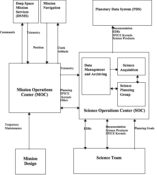
Figure
2 MESSENGER Data Flow shows the flow of data within the MESSENGER project and
out to PDS. The MOC handles raw data flow to and from the MESSENGER
spacecraft and the SOC converts the raw telemetry into EDRs. The Science Team
validates the EDRs and notifies the SOC if corrections are needed.
Documentation, EDRs, and science products are delivered to the PDS Planetary
Plasma Interactions (PPI) node. SPICE kernels are delivered to the PDS
Navigation and Ancillary Information (NAIF) node. The delivery process is
detailed below.
The MESSENGER SOC will
deliver data for the EPPS EDR data volume to the PDS PPI Node in standard
product packages. Each package will comprise data and ancillary data files,
organized into directory structures consistent with the volume design described
in section 6.8.
The initial release will also contain the documents and required files for the
EPPS documentation volume, organized into directory structures as described in
section 6.7.
Subsequent releases to the EPPS documentation volume will be at the discretion
of the EPPS team and be delivered whenever the EPPS team determines that they
have a sufficiently improved calibration to warrant a new release.
The following describes the electronic transfer process of
releasing data to PDS for both the data volume and the documentation volume.
This process will be implemented for the first PDS delivery. Future data
deliveries will be assumed to follow the same process unless otherwise noted in
an update of this document. Given the long duration of the mission the project
reserves the option of exploring alternate data delivery methods for subsequent
deliveries. As such, the method of electronic transfer may change and will be
revised accordingly in the SIS. Any changes to the delivery process will be
noted in an update to the SIS document and will include the specific dates which
will use the new delivery process. The delivery of products to the data volume
will follow the schedule in the MESSENGER Data Management and Archiving Plan.
The delivery date for updates to the documentation volume will be determined as
needed at the discretion of the EPPS team.
In the week prior to the delivery date the directory
structure will be compressed into a single “zip archive” file for transmittal
to the PDS node. The zip archive preserves the directory structure internally
so that it can be recreated after electronic delivery to the PDS node. The zip
archive file is transmitted to the PDS node via FTP to an account set up by the
receiving node. Also transmitted will be a checksum file created using the MD5
algorithm. This provides an independent method of verifying the integrity of
the zip file after it has been sent. Within days of transmittal the PDS node
will acknowledge receipt of the archive and checksum file. If acknowledgement
is not received, or if problems are reported, the MESSENGER SOC will
immediately take corrective action to effect successful transmittal.
After transmittal the PDS node will uncompress the zip
archive file and check for data integrity using the checksum file. The node
will then perform any additional verification and validation of the data
provided and will report any discrepancies or problems to the MESSENGER SOC. It
is expected that the node will perform these checks in about two weeks. After
inspection has been completed to the satisfaction of the PDS node, the node
will issue to the MESSENGER SOC acknowledgement of successful receipt of the
data.
Following receipt of a data delivery the PDS node will
organize the data into a PDS volume archive structure within its online data
system. Newly delivered data will be made available publicly from PDS once
accompanying labels and other documentation have been validated.
The PDS label conforms to PDS
version 3.6 standards. For more information about this standard consult the PDS
Standards Reference Document. The label is detached and in a separate PDS label
file. The purpose of the PDS label is to describe the data product and provide
ancillary information about the data product. There is a PDS label file for
every EPPS EDR data file. There is one DATA_SET_ID assigned to the EPPS EDR
data. The EDRs are further grouped into data products and are identified by the
STANDARD_DATA_PRODUCT_ID keyword and the file naming convention, section 6.5. . Example label file
content is shown here for every EDR data product. Note that the data is
contained within a binary table or ASCII table and the details of the table
structure are described by an external ASCII format file (*.FMT). The fields in
each format file are described separately in the Appendix.
5.3.4.1 EPS
High Priority Spectra PDS Label
PDS_VERSION_ID
= "PDS3"
/***
FILE FORMAT ***/
FILE_RECORDS
= 287
RECORD_TYPE
= FIXED_LENGTH
RECORD_BYTES
= 1756
/***
GENERAL DATA DESCRIPTION PARAMETERS ***/
PRODUCT_ID
= "EPSH_S2005134EDR_V1_DAT"
PRODUCT_VERSION_ID
= "V1"
PRODUCT_CREATION_TIME
= 2007-11-12T16:05:31
PRODUCT_TYPE
= "DATA"
STANDARD_DATA_PRODUCT_ID =
"EPS_HI_SPECTRA"
SOFTWARE_NAME
= "PIPE-EPPS2EDR"
SOFTWARE_VERSION_ID
= "1.0"
INSTRUMENT_HOST_NAME
= "MESSENGER"
INSTRUMENT_NAME
= "ENERGETIC PARTICLE SPECTROMETER"
INSTRUMENT_ID
= "EPS"
DATA_SET_ID
=
"MESS-E/V/H/SW-EPPS-2-EPS-RAWDATA-V1.0"
DATA_SET_NAME
= "MESSENGER E/V/H/SW EPPS UNCALIBRATED EPS EDR V1.0"
MISSION_PHASE_NAME
= "EARTH CRUISE"
TARGET_NAME
= "CALIBRATION"
START_TIME
= 2005-05-14T00:04:51
STOP_TIME
= 2005-05-14T23:56:42
SPACECRAFT_CLOCK_START_COUNT = "24516235"
SPACECRAFT_CLOCK_STOP_COUNT = "24602146"
^TABLE
= "EPSH_S2005134EDR_V1.DAT"
OBJECT
= TABLE
COLUMNS =
67
INTERCHANGE_FORMAT
= BINARY
ROW_BYTES
= 1756
ROWS
= 287
DESCRIPTION
= "
This table contains spectral
data collected by the MESSENGER EPS
instrument in High Priority
Mode.
The complete column
definitions are contained in an external file
found in the LABEL directory
of the archive volume. Additional
details are contained in the
EDR SIS document.
"
^STRUCTURE
= "EPSHIGH.FMT"
END_OBJECT
= TABLE
END
5.3.4.2 EPS
High Priority Housekeeping PDS Label
PDS_VERSION_ID
= "PDS3"
/***
FILE FORMAT ***/
FILE_RECORDS
= 287
RECORD_TYPE
= FIXED_LENGTH
RECORD_BYTES
= 221
/***
GENERAL DATA DESCRIPTION PARAMETERS ***/
PRODUCT_ID
= "EPSH_H2005134EDR_V1_TAB"
PRODUCT_VERSION_ID
= "V1"
PRODUCT_CREATION_TIME
= 2007-11-12T16:05:40
PRODUCT_TYPE
= "ANCILLARY"
STANDARD_DATA_PRODUCT_ID =
"EPS_HI_HOUSEKEEPING"
SOFTWARE_NAME
= "PIPE-EPPS2EDR"
SOFTWARE_VERSION_ID
= "1.0"
INSTRUMENT_HOST_NAME
= "MESSENGER"
INSTRUMENT_NAME
= "ENERGETIC PARTICLE SPECTROMETER"
INSTRUMENT_ID
= "EPS"
DATA_SET_ID
= "MESS-E/V/H/SW-EPPS-2-EPS-RAWDATA-V1.0"
DATA_SET_NAME
= "MESSENGER E/V/H/SW EPPS UNCALIBRATED EPS EDR V1.0"
MISSION_PHASE_NAME
= "EARTH CRUISE"
TARGET_NAME
= "CALIBRATION"
START_TIME
= 2005-05-14T00:04:51
STOP_TIME
= 2005-05-14T23:56:42
SPACECRAFT_CLOCK_START_COUNT = "24516235"
SPACECRAFT_CLOCK_STOP_COUNT = "24602146"
^TABLE
= "EPSH_H2005134EDR_V1.TAB"
OBJECT
= TABLE
COLUMNS
= 34
INTERCHANGE_FORMAT
= ASCII
ROW_BYTES
= 221
ROWS
= 287
DESCRIPTION
= "
This table contains the
housekeeping data created by the EPS instrument in
High Priority Mode. This
table is in ASCI format to facilitate the easy
browsing of instrument
parameters.
The complete column
definitions are contained in an external file found in
the LABEL directory of the archive
volume. Additional details are
contained in the EDR SIS
document.
"
^STRUCTURE
= "EPSHI_HK.FMT"
END_OBJECT
= TABLE
END
5.3.4.3 EPS
Medium Priority Spectra PDS Label
PDS_VERSION_ID
= "PDS3"
/***
FILE FORMAT ***/
FILE_RECORDS
= 2873
RECORD_TYPE
= FIXED_LENGTH
RECORD_BYTES
= 1252
/***
GENERAL DATA DESCRIPTION PARAMETERS ***/
PRODUCT_ID
= "EPSM_S2005134EDR_V1_DAT"
PRODUCT_VERSION_ID
= "V1"
PRODUCT_CREATION_TIME
= 2007-11-12T16:05:49
PRODUCT_TYPE
= "DATA"
STANDARD_DATA_PRODUCT_ID =
"EPS_MED_SPECTRA"
SOFTWARE_NAME
= "PIPE-EPPS2EDR"
SOFTWARE_VERSION_ID =
"2.1"
INSTRUMENT_HOST_NAME
= "MESSENGER"
INSTRUMENT_NAME
= "ENERGETIC PARTICLE SPECTROMETER"
INSTRUMENT_ID
= "EPS"
DATA_SET_ID
= "MESS-E/V/H/SW-EPPS-2-EPS-RAWDATA-V1.0"
DATA_SET_NAME
= "MESSENGER E/V/H/SW EPPS UNCALIBRATED EPS EDR V1.0"
MISSION_PHASE_NAME
= "EARTH CRUISE"
TARGET_NAME
= "CALIBRATION"
START_TIME
= 2005-05-14T00:00:09
STOP_TIME
= 2005-05-14T23:59:31
SPACECRAFT_CLOCK_START_COUNT = "24515953"
SPACECRAFT_CLOCK_STOP_COUNT = "24602315"
^TABLE
= "EPSM_S2005134EDR_V1.DAT"
OBJECT
= TABLE
COLUMNS
= 49
INTERCHANGE_FORMAT
= BINARY
ROW_BYTES
= 1252
ROWS
= 2873
DESCRIPTION
= "
This table contains spectral
data collected by the MESSENGER EPS
instrument in Medium
Priority Mode.
The complete column
definitions are contained in an external file
found in the LABEL directory
of the archive volume. Additional
details are contained in the
EDR SIS document.
"
^STRUCTURE
= "EPSMED.FMT"
END_OBJECT
= TABLE
END
5.3.4.4 EPS
PHA PDS Label
The format for the EPS High,
Medium, Low PHA PDS Labels are identical in terms of the PDS keywords
used. In addition, the format of
the PHA_TABLE object is the same for all EPS PHA EDRs. Therefore, only one
FORMAT file is used to describe all PHA_TABLE objects. The file naming convention will
distinguish whether the EPS PHA EDR contains high, medium, or low priority PHA
data.
After the FSW6 upload, the only
packet which may contain EPS PHA events is the EPS PHA packet. There is
no longer any association with high, medium or low priority as of FSW6 for EPS
PHA EDRs. Section 6.5 File Naming Conventions will explain the designation for
N/A priority in the filename.
A sample High Priority PDS label is shown below:
PDS_VERSION_ID
= "PDS3"
/*** FILE FORMAT ***/
FILE_RECORDS
= 2870
RECORD_TYPE
= FIXED_LENGTH
RECORD_BYTES
= 36
/*** GENERAL DATA DESCRIPTION PARAMETERS ***/
PRODUCT_ID
= "EPSH_P2005134EDR_V2_DAT"
PRODUCT_VERSION_ID
= "V1"
PRODUCT_CREATION_TIME
= 2008-09-16T17:23:43
PRODUCT_TYPE
= "DATA"
STANDARD_DATA_PRODUCT_ID =
"EPS_PULSE_HEIGHT"
SOFTWARE_NAME
= "PIPE-EPPS2EDR"
SOFTWARE_VERSION_ID
= "2.1"
INSTRUMENT_HOST_NAME
= "MESSENGER"
INSTRUMENT_NAME
= "ENERGETIC PARTICLE SPECTROMETER"
INSTRUMENT_ID
= "EPS"
DATA_SET_ID
= "MESS-E/V/H/SW-EPPS-2-EPS-RAWDATA-V1.0"
DATA_SET_NAME = "MESSENGER E/V/H/SW EPPS
UNCALIBRATED EPS EDR V1.0"
MISSION_PHASE_NAME
= "EARTH CRUISE"
TARGET_NAME
= "CALIBRATION"
START_TIME
= 2005-05-14T00:04:51
STOP_TIME
= 2005-05-14T00:04:51
SPACECRAFT_CLOCK_START_COUNT = "24516235"
SPACECRAFT_CLOCK_STOP_COUNT = "24602146"
^TABLE
= "EPSH_P2005134EDR_V2.DAT"
OBJECT
= TABLE
COLUMNS
= 14
INTERCHANGE_FORMAT
= BINARY
ROW_BYTES
= 36
ROWS
= 2870
DESCRIPTION
= "
This table contains the Pulse Height Analysis (PHA) data collected by
the MESSENGER EPS instrument.
The complete column definitions are contained in an external file found
in the LABEL directory of the archive volume. Additional details are
contained in the EDR SIS document.
"
^STRUCTURE = "EPS_PHA.FMT"
END_OBJECT
= TABLE
END
5.3.4.5 EPS
High Resolution Spectra PDS Label
The High Resolution EPS Spectra
EDR was created as the result of the FSW6 upload. It stores the high resolution
ion and electron spectral data collected by the EPS instrument.
PDS_VERSION_ID
= "PDS3"
/*** FILE FORMAT ***/
FILE_RECORDS =
96
RECORD_TYPE
= FIXED_LENGTH
RECORD_BYTES
= 1736
/*** GENERAL DATA DESCRIPTION PARAMETERS ***/
PRODUCT_ID
= "EPSH_R2008233EDR_V1_DAT"
PRODUCT_VERSION_ID
= "V1"
PRODUCT_CREATION_TIME
= 2008-09-24T15:57:14
PRODUCT_TYPE
= "DATA"
STANDARD_DATA_PRODUCT_ID =
"EPS_HIRES_SPECTRA"
SOFTWARE_NAME
= "PIPE-EPPS2EDR"
SOFTWARE_VERSION_ID
= "2.1"
INSTRUMENT_HOST_NAME
=
"MESSENGER"
INSTRUMENT_NAME
= "ENERGETIC PARTICLE SPECTROMETER"
INSTRUMENT_ID
= "EPS"
DATA_SET_ID
= "MESS-E/V/H/SW-EPPS-2-EPS-RAWDATA-V1.0"
DATA_SET_NAME = "MESSENGER E/V/H/SW EPPS
UNCALIBRATED EPS EDR V1.0"
MISSION_PHASE_NAME
= "MERCURY 2 CRUISE"
TARGET_NAME
= "CALIBRATION"
START_TIME
= 2008-08-20T16:00:21
STOP_TIME
= 2008-08-20T23:55:22
SPACECRAFT_CLOCK_START_COUNT = "127735465"
SPACECRAFT_CLOCK_STOP_COUNT = "127763966"
^TABLE
= "EPSH_R2008233EDR_V1.DAT"
OBJECT
= TABLE
COLUMNS
= 15
INTERCHANGE_FORMAT
= BINARY
ROW_BYTES
= 1736
ROWS
= 96
DESCRIPTION
= "
This table contains high-resolution spectra data collected by
the MESSENGER EPS instrument.
The complete column definitions are contained in an external file found
in the LABEL directory of the archive volume. Additional details are
contained in the EDR SIS document.
"
^STRUCTURE = "EPS_HIRES.FMT"
END_OBJECT
= TABLE
END
5.3.4.6 EPS
Low Resolution Spectra PDS Label
The Low Resolution EPS Spectra EDR
was created as the result of the FSW6 upload. It stores the low resolution ion
and electron spectral data as well as 33 rate counters collected by the EPS
instrument.
PDS_VERSION_ID
= "PDS3"
/*** FILE FORMAT ***/
FILE_RECORDS
=
29
RECORD_TYPE
= FIXED_LENGTH
RECORD_BYTES
= 1422
/*** GENERAL DATA DESCRIPTION PARAMETERS ***/
PRODUCT_ID
= "EPSL_R2008231EDR_V1_DAT"
PRODUCT_VERSION_ID
= "V1"
PRODUCT_CREATION_TIME
= 2008-09-22T12:00:40
PRODUCT_TYPE
= "DATA"
STANDARD_DATA_PRODUCT_ID =
"EPS_LORES_SPECTRA"
SOFTWARE_NAME
= "PIPE-EPPS2EDR"
SOFTWARE_VERSION_ID
= "2.1"
INSTRUMENT_HOST_NAME
= "MESSENGER"
INSTRUMENT_NAME
= "ENERGETIC PARTICLE SPECTROMETER"
INSTRUMENT_ID
= "EPS"
DATA_SET_ID
= "MESS-E/V/H/SW-EPPS-2-EPS-RAWDATA-V1.0"
DATA_SET_NAME = "MESSENGER E/V/H/SW EPPS
UNCALIBRATED EPS EDR V1.0"
MISSION_PHASE_NAME
= "MERCURY 2 CRUISE"
TARGET_NAME
= "CALIBRATION"
START_TIME
= 2008-08-18T23:28:23
STOP_TIME
= 2008-08-18T23:56:23
SPACECRAFT_CLOCK_START_COUNT = "127589546"
SPACECRAFT_CLOCK_STOP_COUNT = "127591226"
^TABLE
= "EPSL_R2008231EDR V1.DAT"
OBJECT
= TABLE
COLUMNS
= 92
INTERCHANGE_FORMAT
= BINARY
ROW_BYTES
= 1422
ROWS
= 29
DESCRIPTION
= "
This table contains low-resolution spectra data collected by
the MESSENGER EPS instrument.
The complete column definitions are contained in an external file found
in the LABEL directory of the archive volume. Additional details are
contained in the EDR SIS document.
"
^STRUCTURE = "EPS_LORES.FMT"
END_OBJECT
= TABLE
END
5.3.4.7 EPS
Summary Spectra PDS Label
The EPS Summary Spectra EDR was
created as the result of the FSW6 upload. It contains integrated rates and low
resolution spectra collected by the EPS instrument.
PDS_VERSION_ID
= "PDS3"
/*** FILE FORMAT ***/
FILE_RECORDS
= 95
RECORD_TYPE
= FIXED_LENGTH
RECORD_BYTES
= 716
/*** GENERAL DATA DESCRIPTION PARAMETERS ***/
PRODUCT_ID
= "EPSS_S2008233EDR_V1_DAT"
PRODUCT_VERSION_ID
= "V1"
PRODUCT_CREATION_TIME
= 2008-09-24T15:57:25
PRODUCT_TYPE =
"DATA"
STANDARD_DATA_PRODUCT_ID =
"EPS_SUMMARY_SPECTRA"
SOFTWARE_NAME
= "PIPE-EPPS2EDR"
SOFTWARE_VERSION_ID
= "2.1"
INSTRUMENT_HOST_NAME
= "MESSENGER"
INSTRUMENT_NAME
= "ENERGETIC PARTICLE SPECTROMETER"
INSTRUMENT_ID
= "EPS"
DATA_SET_ID
= "MESS-E/V/H/SW-EPPS-2-EPS-RAWDATA-V1.0"
DATA_SET_NAME = "MESSENGER E/V/H/SW EPPS
UNCALIBRATED EPS EDR V1.0"
MISSION_PHASE_NAME
= "MERCURY 2 CRUISE"
TARGET_NAME
= "CALIBRATION"
START_TIME
= 2008-08-20T16:05:22
STOP_TIME
= 2008-08-20T23:55:22
SPACECRAFT_CLOCK_START_COUNT = "127735766"
SPACECRAFT_CLOCK_STOP_COUNT = "127763966"
^TABLE
=
"EPSS_S2008233EDR V1.DAT"
OBJECT
= TABLE
COLUMNS
= 48
INTERCHANGE_FORMAT
= BINARY
ROW_BYTES
= 716
ROWS
= 95
DESCRIPTION
=
"
This table contains summary spectra data collected by
the MESSENGER EPS instrument.
The complete column definitions are contained in an external file found
in the LABEL directory of the archive volume. Additional details are
contained in the EDR SIS document.
"
^STRUCTURE = "EPS_SUM.FMT"
END_OBJECT
= TABLE
END
5.3.4.8 EPS
Scan PDS Label
The EPS Scan EDR was created as
the result of the FSW6 upload. It contains integrated hardware rate for four
energy threshold settings. Each threshold setting and integration lasts
¼ second.
PDS_VERSION_ID
= "PDS3"
/*** FILE FORMAT ***/
FILE_RECORDS
= 1
RECORD_TYPE
= FIXED_LENGTH
RECORD_BYTES
= 388
/*** GENERAL DATA DESCRIPTION PARAMETERS ***/
PRODUCT_ID
= "EPSS_R2008233EDR_V1_DAT"
PRODUCT_VERSION_ID
= "V1"
PRODUCT_CREATION_TIME
= 2008-09-22T13:00:36
PRODUCT_TYPE
= "DATA"
STANDARD_DATA_PRODUCT_ID =
"EPS_SCAN_RATES"
SOFTWARE_NAME
= "PIPE-EPPS2EDR"
SOFTWARE_VERSION_ID
= "2.1"
INSTRUMENT_HOST_NAME
= "MESSENGER"
INSTRUMENT_NAME
= "ENERGETIC PARTICLE SPECTROMETER"
INSTRUMENT_ID
= "EPS"
DATA_SET_ID
= "MESS-E/V/H/SW-EPPS-2-EPS-RAWDATA-V1.0"
DATA_SET_NAME = "MESSENGER E/V/H/SW EPPS
UNCALIBRATED EPS EDR V1.0"
MISSION_PHASE_NAME
= "MERCURY 2 CRUISE"
TARGET_NAME
= "CALIBRATION"
START_TIME
= 2008-08-20T16:05:21
STOP_TIME
= 2008-08-20T16:05:21
SPACECRAFT_CLOCK_START_COUNT = "127735765"
SPACECRAFT_CLOCK_STOP_COUNT = "127735765"
^TABLE
= "EPSS_R2008233EDR V1.DAT"
OBJECT
=
TABLE
COLUMNS
= 97
INTERCHANGE_FORMAT
= BINARY
ROW_BYTES
= 388
ROWS
= 1
DESCRIPTION
= "
This table contains scan rates collected by the MESSENGER EPS
instrument.
The complete column definitions are contained in an external file found
in the LABEL directory of the archive volume. Additional details are
contained in the EDR SIS document.
"
^STRUCTURE = "EPS_SCAN.FMT"
END_OBJECT
= TABLE
END
The
following are example label headers for the FIPS EDR products. As with the EPS
EDRs all table structures are defined by external format files. The fields in
each format file are defined separately in the Appendix.
5.3.4.9 FIPS High Priority Spectra PDS
Label
A
FSW7 upload was implemented on 8/18/2009 which retired the FIPS High Priority
Spectra packet. As a result, the FIPS High Priority Spectra EDR is no longer
generated on or after 8/18/2009.
PDS_VERSION_ID
=
"PDS3"
/*** FILE FORMAT ***/
FILE_RECORDS
= 149
RECORD_TYPE
= FIXED_LENGTH
RECORD_BYTES
= 4614
/*** GENERAL DATA DESCRIPTION PARAMETERS ***/
PRODUCT_ID
= "FIPH_S2005214EDR_V2_DAT"
PRODUCT_VERSION_ID
= "V2"
PRODUCT_CREATION_TIME
= 2008-02-22T17:35:53
PRODUCT_TYPE
= "DATA"
STANDARD_DATA_PRODUCT_ID =
"FIPS_HI_SPECTRA"
SOFTWARE_NAME
= "PIPE-EPPS2EDR"
SOFTWARE_VERSION_ID
= "2.1"
INSTRUMENT_HOST_NAME
= "MESSENGER"
INSTRUMENT_NAME
= "FAST IMAGING PLASMA SPECTROMETER"
INSTRUMENT_ID
= "FIPS"
DATA_SET_ID
= "MESS-E/V/H/SW-EPPS-2-FIPS-RAWDATA-V1.0"
DATA_SET_NAME = "MESSENGER E/V/H/SW EPPS UNCALIBRATED FIPS
EDR V1.0"
MISSION_PHASE_NAME
= "EARTH FLYBY"
TARGET_NAME
= "EARTH"
START_TIME
= 2005-08-02T00:00:55
STOP_TIME
= 2005-08-02T23:53:36
SPACECRAFT_CLOCK_START_COUNT = "31427999"
SPACECRAFT_CLOCK_STOP_COUNT = "31513960"
^TABLE
= "FIPH_S2005214EDR_V2.DAT"
OBJECT
= TABLE
COLUMNS
= 19
INTERCHANGE_FORMAT =
BINARY
ROW_BYTES
= 4614
ROWS
= 149
DESCRIPTION
= "
This
table contains the following data gathered by the Fast Imaging
Plasma
Spectrometer (FIPS) in HIGH priority mode:
-Proton
velocity distribution
The table
also contains hardware and software rate counts accumulated
over each
separate observation.
The
complete column definitions are contained in an external file
found in
the LABEL directory of the archive volume.
Additional
details
are contained in the EDR SIS document.
"
^STRUCTURE = "FIPS_HI.FMT"
END_OBJECT
= TABLE
END
5.3.4.10 FIPS High Priority Housekeeping PDS
Label
A
FSW5 upload was implemented on 9/6/2007. The upload moved the housekeeping data
from the FIPS High Priority packet to the EPPS Long Status packet. As a result,
the FIPS Housekeeping EDR is no longer generated on or after 9/6/2007.
PDS_VERSION_ID
= "PDS3"
/*** FILE FORMAT ***/
FILE_RECORDS =
149
RECORD_TYPE
= FIXED_LENGTH
RECORD_BYTES
= 216
/*** GENERAL DATA DESCRIPTION PARAMETERS ***/
PRODUCT_ID
= "FIPH_H2005214EDR_V2_TAB"
PRODUCT_VERSION_ID
= "V2"
PRODUCT_CREATION_TIME
= 2008-02-22T17:35:53
PRODUCT_TYPE
= "ANCILLARY"
STANDARD_DATA_PRODUCT_ID =
"FIPS_HI_HOUSEKEEPING"
SOFTWARE_NAME
= "PIPE-EPPS2EDR"
SOFTWARE_VERSION_ID
= "2.0"
INSTRUMENT_HOST_NAME =
"MESSENGER"
INSTRUMENT_NAME
= "FAST IMAGING PLASMA SPECTROMETER"
INSTRUMENT_ID
= "FIPS"
DATA_SET_ID
= "MESS-E/V/H/SW-EPPS-2-FIPS-RAWDATA-V1.0"
DATA_SET_NAME = "MESSENGER E/V/H/SW EPPS
UNCALIBRATED FIPS EDR V1.0"
MISSION_PHASE_NAME
= "EARTH FLYBY"
TARGET_NAME
= "EARTH"
START_TIME
= 2005-08-02T00:00:55
STOP_TIME
= 2005-08-02T23:53:36
SPACECRAFT_CLOCK_START_COUNT = "31427999"
SPACECRAFT_CLOCK_STOP_COUNT = "31513960"
^TABLE
= "FIPH_H2005214EDR_V2.TAB"
OBJECT
= TABLE
COLUMNS
= 32
INTERCHANGE_FORMAT
= ASCII
ROW_BYTES
= 216
ROWS
= 149
DESCRIPTION
= "
This table contains the housekeeping data created by the FIPS instrument
in
HIGH Priority Mode. The complete column definitions are contained in an
external file found in the LABEL directory of the archive volume.
Additional details are contained in the EDR SIS document.
"
^STRUCTURE = "FIPS_HK.FMT"
END_OBJECT
= TABLE
END
5.3.4.11 FIPS Medium Priority PDS Label
A
FSW6 upload was implemented on 8/19/2008. The upload retired the Medium
Priority packet and split the contents into two new packets. As a result, the
Medium Priority EDR is no longer created after 8/19/2008. Data from the two new
packets are contained in the FIPS Scan and FIPS Hi-Res Proton Velocity Distribution
EDRs.
PDS_VERSION_ID
= "PDS3"
/*** FILE FORMAT ***/
FILE_RECORDS
= 1337
RECORD_TYPE
= FIXED_LENGTH
RECORD_BYTES
= 1542
/*** GENERAL DATA DESCRIPTION PARAMETERS ***/
PRODUCT_ID
= "FIPM_S2005214EDR_V2_DAT"
PRODUCT_VERSION_ID
= "V2"
PRODUCT_CREATION_TIME
= 2008-02-23T00:35:23
PRODUCT_TYPE
= "DATA"
STANDARD_DATA_PRODUCT_ID =
"FIPS_MED_SPECTRA"
SOFTWARE_NAME
=
"PIPE-EPPS2EDR"
SOFTWARE_VERSION_ID
= "2.0"
INSTRUMENT_HOST_NAME
= "MESSENGER"
INSTRUMENT_NAME
= "FAST IMAGING PLASMA SPECTROMETER"
INSTRUMENT_ID
= "FIPS"
DATA_SET_ID
= "MESS-E/V/H/SW-EPPS-2-FIPS-RAWDATA-V1.0"
DATA_SET_NAME = "MESSENGER E/V/H/SW EPPS
UNCALIBRATED FIPS EDR V1.0"
MISSION_PHASE_NAME
= "EARTH FLYBY"
TARGET_NAME
= "EARTH"
START_TIME
= 2005-08-02T00:01:53
STOP_TIME
= 2005-08-02T23:59:24
SPACECRAFT_CLOCK_START_COUNT = "31428057"
SPACECRAFT_CLOCK_STOP_COUNT = "31514308"
^TABLE
= "FIPM_S2005214EDR_V2.DAT"
OBJECT
= TABLE
COLUMNS
= 8
INTERCHANGE_FORMAT
= BINARY
ROW_BYTES
= 1542
ROWS
= 1337
DESCRIPTION
= "
This table contains the following data gathered by the Fast Imaging
Plasma Spectrometer (FIPS) in MEDIUM priority mode:
-Proton velocity
distribution
The table also contains hardware and software rate counts accumulated
over each separate observation.
The complete column definitions are contained in an external file
found in the LABEL directory of the archive volume. Additional
details are contained in the EDR SIS document.
"
^STRUCTURE = "FIPS_MED.FMT"
END_OBJECT
= TABLE
END
5.3.4.12 FIPS PHA PDS Label
The format for the FIPS High,
Medium, Low PHA PDS Labels are identical in terms of the PDS keywords
used. In addition, the format of
the PHA_TABLE object is the same for all FIPS PHA EDRs. Therefore, only one
FORMAT file is used to describe all PHA_TABLE objects. The file naming convention will
distinguish whether the FIPS PHA EDR contains high, medium, or low priority PHA
data.
After the FSW6 upload, the only
packets which may contain PHA events are the high priority, low priority, and
scan packets (medium priority packets being retired). The file naming
convention will distinguish whether the FIPS PHA EDR contains PHA events
extracted from high or low priority, or
scan packets. This is detailed in Section 6.5.
After the FSW7 upload, the only
packets which may contain PHA events are the Heavy Ion packet and Proton packet
(Scan and Low Priority packets being retired). Because of this the PHA file
naming convention is simplified to show the year, day of year, and the fact
that the file contains PHA events. This is detailed in Section 6.5.
A sample FSW7 PDS label is shown below:
PDS_VERSION_ID
= "PDS3"
/*** FILE FORMAT ***/
FILE_RECORDS
= 171488
RECORD_TYPE
= FIXED_LENGTH
RECORD_BYTES
= 38
/*** GENERAL DATA DESCRIPTION
PARAMETERS ***/
PRODUCT_ID
= "FIPP_P2009274EDR_V1_DAT"
PRODUCT_VERSION_ID
= "V1"
PRODUCT_CREATION_TIME
= 2009-10-02T11:57:24
PRODUCT_TYPE
= "DATA"
STANDARD_DATA_PRODUCT_ID =
"FIPS_PULSE_HEIGHT"
SOFTWARE_NAME
= "PIPE-EPPS2EDR"
SOFTWARE_VERSION_ID
= "2.1"
INSTRUMENT_HOST_NAME
= "MESSENGER"
INSTRUMENT_NAME
= "ENERGETIC PARTICLE AND PLASMA SPECTROMETER"
INSTRUMENT_ID
= "EPPS"
DATA_SET_ID
= "MESS-E/V/H/SW-EPPS-2-FIPS-RAWDATA-V2.0"
DATA_SET_NAME =
"MESSENGER E/V/H/SW EPPS UNCALIBRATED FIPS EDR V2.0"
MISSION_PHASE_NAME
= "MERCURY 3 FLYBY"
TARGET_NAME
= "MERCURY"
START_TIME
=
2009-10-01T19:10:49
STOP_TIME
= 2009-10-01T23:59:28
SPACECRAFT_CLOCK_START_COUNT = "162911715"
SPACECRAFT_CLOCK_STOP_COUNT = "162929034"
^TABLE
= "FIPP_P2009274EDR_V1.DAT"
OBJECT
=
TABLE
COLUMNS
= 10
INTERCHANGE_FORMAT
= BINARY
ROW_BYTES
= 38
ROWS
= 171488
DESCRIPTION
= "
This table contains the
Pulse Height Analysis (PHA) data collected by
the MESSENGER Fast Imaging
Plasma Spectrometer (FIPS).
The complete column
definitions are contained in an external file found
in the LABEL directory of
the archive volume. Additional details are
contained in the EDR SIS
document.
"
^STRUCTURE =
"FIPS_PHA.FMT"
END_OBJECT
= TABLE
END


5.3.4.13 FIPS
Scan PDS Label
The FIPS Scan EDR was created as
the result of the FSW6 upload. It contains FIPS rate counters sampled at each
DSHV step in a scan. This EDR has been retired as a result of the FSW7 upload
on 8/18/2009 and is no longer generated on or after that date.
PDS_VERSION_ID
= "PDS3"
/*** FILE FORMAT ***/
FILE_RECORDS
= 387
RECORD_TYPE
= FIXED_LENGTH
RECORD_BYTES
= 1286
/*** GENERAL DATA DESCRIPTION PARAMETERS ***/
PRODUCT_ID
= "FIPS_R2008233EDR_V1_DAT"
PRODUCT_VERSION_ID
= "V1"
PRODUCT_CREATION_TIME
= 2008-09-22T13:00:23
PRODUCT_TYPE =
"DATA"
STANDARD_DATA_PRODUCT_ID =
"FIPS_SCAN"
SOFTWARE_NAME
= "PIPE-EPPS2EDR"
SOFTWARE_VERSION_ID
= "2.1"
INSTRUMENT_HOST_NAME
= "MESSENGER"
INSTRUMENT_NAME
= "FAST IMAGING PLASMA SPECTROMETER"
INSTRUMENT_ID
= "FIPS"
DATA_SET_ID
= "MESS-E/V/H/SW-EPPS-2-FIPS-RAWDATA-V1.0"
DATA_SET_NAME = "MESSENGER E/V/H/SW EPPS
UNCALIBRATED FIPS EDR V1.0"
MISSION_PHASE_NAME
= "MERCURY 2 CRUISE"
TARGET_NAME
= "CALIBRATION"
START_TIME
= 2008-08-20T16:02:28
STOP_TIME
= 2008-08-20T23:59:13
SPACECRAFT_CLOCK_START_COUNT = "127735592"
SPACECRAFT_CLOCK_STOP_COUNT = "127764197"
^TABLE
=
"FIPS_R2008233EDR V1.DAT"
OBJECT
= TABLE
COLUMNS
= 7
INTERCHANGE_FORMAT
= BINARY
ROW_BYTES
= 1286
ROWS
= 387
DESCRIPTION
= "
This table contains the FIPS rate counts gathered by the Fast Imaging
Plasma Spectrometer (FIPS)accumulated over each separate observation.
The complete column definitions are contained in an external file found
in the LABEL directory of the archive volume. Additional details are
contained in the EDR SIS document.
"
^STRUCTURE = "FIPS_SCAN.FMT"
END_OBJECT
= TABLE
END
5.3.4.14 FIPS
High Resolution Proton Velocity Distribution (HRPVD) PDS Label
The FIPS HRPVD EDR was created as
the result of the FSW6 upload. It contains a 32 x 32 high resolution proton
velocity distribution, integrated over a 10 scan sequence. This EDR has been
retired as a result of the FSW7 upload on 8/18/2009 and is no longer generated
on or after that date.
PDS_VERSION_ID
= "PDS3"
/*** FILE FORMAT ***/
FILE_RECORDS
= 42
RECORD_TYPE
= FIXED_LENGTH
RECORD_BYTES
= 4118
/*** GENERAL DATA DESCRIPTION PARAMETERS ***/
PRODUCT_ID
=
"FIPS_V2008233EDR_V1_DAT"
PRODUCT_VERSION_ID
= "V1"
PRODUCT_CREATION_TIME
= 2008-09-22T13:00:26
PRODUCT_TYPE
= "DATA"
STANDARD_DATA_PRODUCT_ID =
"FIPS_HIRES_PROTON_V"
SOFTWARE_NAME
= "PIPE-EPPS2EDR"
SOFTWARE_VERSION_ID
= "2.1"
INSTRUMENT_HOST_NAME
= "MESSENGER"
INSTRUMENT_NAME
= "FAST IMAGING PLASMA SPECTROMETER"
INSTRUMENT_ID
= "FIPS"
DATA_SET_ID
= "MESS-E/V/H/SW-EPPS-2-FIPS-RAWDATA-V1.0"
DATA_SET_NAME = "MESSENGER E/V/H/SW EPPS
UNCALIBRATED FIPS EDR V1.0"
MISSION_PHASE_NAME
= "MERCURY 2 CRUISE"
TARGET_NAME
= "CALIBRATION"
START_TIME
= 2008-08-20T16:12:30
STOP_TIME
= 2008-08-20T23:49:12
SPACECRAFT_CLOCK_START_COUNT = "127736194"
SPACECRAFT_CLOCK_STOP_COUNT = "127763596"
^TABLE
= "FIPS_V2008233EDR V1.DAT"
OBJECT
= TABLE
COLUMNS
=
38
INTERCHANGE_FORMAT
= BINARY
ROW_BYTES
= 4118
ROWS
= 42
DESCRIPTION
= "
This table contains the high-resolution proton velocity distributions
gathered by the Fast Imaging Plasma Spectrometer (FIPS)collected over a 10-scan
sequence.
The complete column definitions are contained in an external file found
in the LABEL directory of the archive volume. Additional details are
contained in the EDR SIS document.
"
^STRUCTURE = "FIPS_HRPVD.FMT"
END_OBJECT
= TABLE
END
5.3.4.15 EPPS
Status PDS Label
The
EPPS Status EDR contains the engineering and status data for the EPPS
instrument. This EDR is no longer
generated on or after 9/6/2007 due to the FSW5 upload; instead use the
EPPS_LONG_STATUS EDR for data on or after 9/6/2007. The content of the EPPS
Status label is shown below:
PDS_VERSION_ID
= "PDS3"
/*** FILE FORMAT ***/
FILE_RECORDS
= 8640
RECORD_TYPE =
"FIXED_LENGTH"
RECORD_BYTES
= 356
/*** GENERAL DATA DESCRIPTION PARAMETERS ***/
PRODUCT_ID
= "EPPS2005121EDR_TAB"
PRODUCT_VERSION_ID
= "V1"
PRODUCT_CREATION_TIME
= 2006-01-11T14:31:46
PRODUCT_TYPE
= "EDR"
STANDARD_DATA_PRODUCT_ID =
"EPPS_STATUS"
SOFTWARE_NAME
= "PIPE-EPPS2EDR"
SOFTWARE_VERSION_ID
= "1.0"
MD5_CHECKSUM
= "abc123abc123abc123abc123"
INSTRUMENT_HOST_NAME
= "MESSENGER"
INSTRUMENT_NAME
= "ENERGETIC PARTICLE AND PLASMA SPECTROMETER"
INSTRUMENT_ID
= "EPPS"
DATA_SET_ID
= "MESS-EDR-EPPS-STATUS-2-CRUISE-V1.0"
DATA_SET_ID
=
{"MESS-E/V/H/SW-EPPS-2-EPS-RAWDATA-V1.0",
"MESS-E/V/H/SW-EPPS-2-FIPS-RAWDATA-V1.0"}
MISSION_PHASE_NAME
= "EARTH CRUISE"
TARGET_NAME
= "CALIBRATION"
START_TIME
= 2005-05-01T00:00:02
STOP_TIME =
2005-05-01T23:59:52
SPACECRAFT_CLOCK_START_COUNT = "23392746"
SPACECRAFT_CLOCK_STOP_COUNT = "23479136"
^TABLE
= "EPPS2005121EDR_V1.TAB"
OBJECT
= TABLE
COLUMNS
= 55
INTERCHANGE_FORMAT
= BINARY
ROW_BYTES
= 356
ROWS
= 8640
DESCRIPTION
= "
This table contains housekeeping and status data collected by the
MESSENGER EPPS instrument.
The complete column definitions are
contained in an external file
found in the LABEL directory of the archive volume. Additional
details are contained in the EDR SIS document.
"
^STRUCTURE = "EPPS_STATUS.FMT"
END_OBJECT
= TABLE
END
5.3.4.16 EPPS
Long Status PDS Label
The EPPS_LONG_STATUS EDR contains the engineering and
status data for the EPPS instrument as generated by the flight software on and
after 9/6/2007 due to the FSW5 upload. The additional columns store
housekeeping data that was previously recorded in the EPS/FIPS High Priority
Housekeeping EDRs.
PDS_VERSION_ID
= "PDS3"
/***
FILE FORMAT ***/
FILE_RECORDS
= 21
RECORD_TYPE
= FIXED_LENGTH
RECORD_BYTES
= 550
/***
GENERAL DATA DESCRIPTION PARAMETERS ***/
PRODUCT_ID
= "ELONG2007348EDR_V1_TAB"
PRODUCT_VERSION_ID
= "V1"
PRODUCT_CREATION_TIME
= 2007-12-20T10:00:38
PRODUCT_TYPE
= "ANCILLARY"
STANDARD_DATA_PRODUCT_ID =
"EPPS_LONG_STATUS"
SOFTWARE_NAME
= "PIPE-EPPS2EDR"
SOFTWARE_VERSION_ID
= "2.1"
INSTRUMENT_HOST_NAME
= "MESSENGER"
INSTRUMENT_NAME
= "ENERGETIC PARTICLE AND PLASMA SPECTROMETER"
INSTRUMENT_ID
= "EPPS"
DATA_SET_ID
=
{"MESS-E/V/H/SW-EPPS-2-EPS-RAWDATA-V1.0",
"MESS-E/V/H/SW-EPPS-2-FIPS-RAWDATA-V1.0"}
MISSION_PHASE_NAME
= "MERCURY 1 CRUISE"
TARGET_NAME
=
"CALIBRATION"
START_TIME
= 2007-12-14T17:43:38
STOP_TIME
= 2007-12-14T23:43:02
SPACECRAFT_CLOCK_START_COUNT = "106141597"
SPACECRAFT_CLOCK_STOP_COUNT = "106163161"
^TABLE
= "ELONG2007348EDR_V1.TAB"
OBJECT
= TABLE
COLUMNS
= 103
INTERCHANGE_FORMAT
= ASCII
ROW_BYTES
= 550
ROWS
= 21
DESCRIPTION
= "
This table contains
housekeeping and status data collected by the
MESSENGER EPPS instrument.
This EDR is the result of the EPPS
Flight Software v5 upload in
which the updated status packet
contains additional
housekeeping values.
The complete column
definitions are contained in an external file
found in the LABEL directory
of the archive volume. Additional
details are contained in the
EDR SIS document.
"
^STRUCTURE
= "EPPS_LONG.FMT"
END_OBJECT
= TABLE
END
The EPPS EDR data products are constructed according to the
data object concepts
developed
by the PDS. By adopting the PDS format, the data products are consistent in content and
organization with other planetary data collections. In the PDS standard, the EDR data file is grouped into objects with PDS
labels describing the objects. Each EDR data product consists of two files:
- A data file containing
an ASCII or binary table object (the primary data), in fixed field format.
- A label file which
serves as a high-level description of the parameters of which correspond
to the data file. The label file contains a pointer to an external format
file which details the structure of the table object in the data file.
The time fields in the EPPS table objects reference the
Mission Elapsed Time (MET). This MET is the spacecraft time in integer seconds
that is transmitted to MESSENGER subsystems by the Integrated Electronics
Module (IEM). This is referred to by the MESSENGER project as Mission Elapsed
Time (MET). MET = 0 is August 3, 2004, at 05:59:16 UTC, which is 1000 seconds
prior to the MESSENGER launch. Relativistic effects and circumstances occurring
during the mission would result in MET not being a true account of seconds
since launch. For this reason the MESSENGER spacecraft clock coefficients file
is archived at the PDS Navigation and Ancillary Information Facility (NAIF)
Node. This file is used in conjunction with the leapseconds kernel file in order
to calculate the conversion between MET and UTC.
The conversion is easily done through the use of SPICE
kernels and the CHRONOS Utility. CHRONOS is a utility included with the SPICE
package that is distributed by the PDS NAIF node. The SPICE kernels are files
that contain the information needed to perform the conversion. Two SPICE
kernels are required. One is the Leapseconds Kernel (LSK) and the other is the
MESSENGER Spacecraft Clock Kernel (SCLK). The SCLK file is used by CHRONOS to
convert between spacecraft clock time and ephemeris time, while the LSK file is
used to convert from ephemeris time to UTC time. The CHRONOS utility is
self-documenting and the SPICE package itself contains full documentation on
each of the utilities (including CHRONOS) and how they are used.
Table 10 lists the computational
assumptions for the geometric and viewing data provided in the PDS label. There
are two coordinate systems in use: 1) the celestial reference system used
for target and spacecraft position and velocity vectors; and 2) the planetary
coordinate system for geometry vectors and target location. The celestial coordinate system is J2000
(Mean of Earth equator and equinox of J2000). The planetary coordinate system
is planetocentric.
Different time series data
products will be provided corresponding to different coordinate systems. These include: inertial celestial (e.g.
J2000), Mercury centered body fixed, Mercury centered magnetospheric, Mercury centered
solar wind, and solar orbital (appropriate for cruise). The detailed definition of
magnetospheric coordinates depend on the orientation of the Hermetian magnetic
dipole and will therefore be updated during the mission.”
Table 11 Computational Assumptions
<> The
mid-point time of observation is used for the geometric
element computations.
<> Label
parameters reflect observed, not true, geometry.
Therefore, light-time and stellar aberration corrections are
used as appropriate.
<> The
inertial reference frame is J2000 (also called EME2000).
<>
Latitudes and longitudes are planetocentric.
<> The
"sub-point" of a body on a target is defined by the surface
intercept of the body-to-target-center vector. This is not
the closest point on the body to the observer.
<>
Distances are in km, speeds in km/sec, angles, in degrees,
angular rates in degrees/sec, unless otherwise noted.
<> Angle
ranges are 0 to 360 degrees for azimuths and local hour
angle. Longitudes range from 0 to 360 degrees
(positive to the East).
Latitudes range from -90 to 90
degrees.
The data are organized following PDS standards and stored on
hard disk and an SQL (Structured Query Language) relational database for rapid
access during mission operations. The MESSENGER SOC will transfer data to PDS
via electronic transfer and delivery methods as detailed in section 5.3.3.
After verification of the data transfer PDS will provide public access to
MESSENGER science data products through its online data distribution system.
The EPPS EDR data archive volume set will include all data
acquired during the MESSENGER mission. The archive validation procedure
described in this section applies to data products generated during all post
launch phases of the mission. To be clear, there is one and only one
documentation volume and one and only one EPPS EDR data archive volume created
over the whole mission. Initial releases of both volumes will occur during the
first EDR delivery date as stated in the schedule in the MESSENGER Data
Management and Archiving Plan. Updates to the data volume will occur according
to the same schedule. Updates to the documentation volume will occur at the
discretion of the EPPS team.
PDS standards recommend that all data included in the formal
archive be validated through a peer-review process. This process is designed to
ensure that both the data and documentation are of sufficient quality to be
useful to future generations of scientists. The schedule of PDS data
deliveries, however, necessitate some modification of the normal PDS review
process since it is impractical to convene a review panel to examine the
archive volume for every PDS data delivery. The following describes the
modified validation process. The process is presented as several steps, most of
which occur in the PDS peer review. This peer review is conducted before any
volumes are produced and released to PDS.
The peer review panel consists of members of the EPPS team,
members of ACT, the PPI node of PDS, and at least one outside scientist
actively working in the field of energetic particles research. The PDS
personnel are responsible for validating that the volumes are fully compliant
with PDS standards. The instrument team, ACT, and outside reviewer(s) are
responsible for verifying the content of the data set, the completeness of the
documentation, and the usability of the data in its archive format.
The peer review will validate the documentation and data
archive volumes via a two step process. First the panel reviews this document
and verifies that the volumes and EDRs produced to this specification will be
useful. Next the panel reviews the initial release of the data and
documentation volumes to verify that the volumes meet this specification and
are acceptable. Once automated production begins, software provided by ACT
produce a summary of each data product and software provided by the PPI node
verifies that all the files required by PDS are present and the files
themselves conform to PDS standards. If an error is detected by either of the
above programs, the error is corrected, if possible, before the update to the
volume is delivered. Otherwise the correction will occur at the next scheduled
delivery date. If an error in a data file is uncorrectable, (i.e. an error in
the downlink data file) the error is described in the cumulative errata file
that is included in the data archive volume.
The peer review will also validate the EPPS EDR data in a
two step process. The first step consists of reviewing a sample data set for
compliance with the PDS standards. The sample data set is delivered and
reviewed in conjunction with delivery and review of this SIS document. The
second step is examination of the data to ensure usability and completeness.
The PDS personnel will be responsible for validating that the EDR data set is
fully compliant with PDS standards. The instrument team, ACT, and the outside
science reviewer(s) will be responsible for verifying the content of the data
set, the completeness of the documentation, and the usability of the data in
its archive format.
Any deficiencies in the archive data or documentation volumes
will be recorded as liens against the product by the review panel. The sample
data set is created using software provided by ACT. Once the sample data is
validated, and all liens placed against the product or product generation
software are resolved, the same software will be used to generate subsequent
data products in an automated fashion.
Once automated production begins, the data file content will
be spot checked by members of the EPPS team. “Quick look” products generated by
software provided by ACT and the EPPS team will be produced routinely and
examined by members of the team. In addition, the data will be actively used by
team members to perform their analysis. Any discrepancies in the data noted
during these activities will be investigated. If the discrepancy is a data
error, the response will depend on the source of the error. If the error is in
the software producing the data product, the error will be corrected and the
data affected will be reproduced, replacing the data file. If there is a correctable
error in a data file, the file will be replaced. If an error in a data file is
uncorrectable, the error will be described in the cumulative errata file
included in the archive volume. The structure of data files and labels will be
spot checked by the PPI node for compliance with PDS standards and this SIS.
The MESSENGER EPPS EDR data products will be archived at the
PDS PPI Node. The EDR data set in the data archive volume is intended to store
the data in a form closest to the raw telemetry data received from the
spacecraft. The automated production and release of EDRs lends itself to the
regular release schedule outlined in the MESSENGER Data Management and
Archiving Plan. If errors are discovered the data will be replaced with
corrected EDRs on the next scheduled delivery date.
Calibration tables and calibration procedures will be
required to properly analyze EDRs. These ancillary data will be archived at the
PDS PPI Node as part of the EPPS documentation volume. The documentation volume
will also be referenced by the EPPS RDR data archive volume. The documentation
volume will therefore include both the EPPS EDR SIS and the EPPS RDR SIS in
addition to the calibration tables, calibration procedures, and other documents
applicable to either data archive volume. A first release of the EPPS
documentation volume will accompany the initial release of the EPPS EDR data
archive. The initial release of the documentation volume will only contain EDR
level documentation and the parameters derived from the ground calibration
tests. After the initial release there will be updates whenever the EPPS team
determines that they have a sufficiently improved calibration to warrant a new release.
The possibility exists that errors may be introduced into
the archive even with validation procedures applied to the archive volumes. An
ERRATA report file is maintained to track and document all discovered
uncorrectable errors that may occur during the mission. Correctable errors,
such as revised EDRs or EDRs that were missing from a previous PDS delivery
will be provided at the next scheduled PDS delivery or at the final delivery
date (schedule in the MESSENGER Data Management and Archiving Plan). PDS will
then replace the outdated files with the revised EDR files in the data
directories of the archive volume. The ERRATA report file is archived in the
ROOT directory of the EPPS EDR data volume.
Data is stored in ASCII table
format or in binary table format .
A detached PDS label file will provide a detailed description of the structure
of each table. See section 5.2 for details on which data product contains a binary table or an ASCII
table.
The following are the keyword
definitions for the detached PDS label file, which accompanies the instrument
data file. The detached PDS label
file has the same name as the data file it describes, except for the extension
.LBL to distinguish it as a label file.
PDS_VERSION_ID
Represents the version number
of the PDS standards documents that is valid when a data product label is
created. PDS3 is used for the MESSENGER data products.
FILE_RECORDS
Indicates the number of
physical file records, including both label records and data records.
RECORD_TYPE
Indicates the record format of
a file. Note: In the PDS, when record_type is used in
a detached label file it always describes its corresponding detached data file,
not the label file itself. The use
of record_type along with other file-related data elements is fully described
in the PDS Standards Reference.
RECORD_BYTES
Indicates the number of bytes
in a physical file record, including record terminators and separators. Note: In the PDS, the use of record_bytes,
along with other file-related data elements is fully described in the Standards
Reference.
PRODUCT_ID
Represents a permanent, unique
identifier assigned to a data product by its producer.
PRODUCT_CREATION_TIME
Defines the UTC system format
time when a product was created.
PRODUCT_VERSION_ID
Identifies the version of an
individual product within a data set.
Example: 1.0, 2.0, 3.0.
Product_version_id will be
incremented if a given EDR has to be regenerated and sent to PDS to replace a
previously submitted EDR.
PRODUCT_TYPE
Identifies the type or category
of a product within a data set.
PRODUCT_TYPE
Identifies the type or category
of a product within a data set.
STANDARD_DATA_PRODUCT_ID
Used to link an EPPS EDR file
to one of the 9 types of EPPS data products defined within the EPPS EDR SIS.
SOFTWARE_NAME
Identifies the data processing
software used to convert from spacecraft telemetry into EDR products.
SOFTWARE_VERSION_ID
Indicates the version of the
data processing software used to generate the EDR products from the spacecraft
telemetry.
MD5_CHECKSUM
Used to verify the successful
electronic transfer of the EDR from the SOC to the PDS-PPI Node.
INSTRUMENT_HOST_NAME
The full name of the host on
which an instrument is based. In
this case it is the MESSENGER spacecraft.
INSTRUMENT_NAME
Provides the full name of the
instrument.
INSTRUMENT_ID
Provides an abbreviated name or
acronym which identifies an instrument.
DATA_SET_ID
The data_set_id element is a
unique alphanumeric identifier for a data set or a data product. The
data_set_id value for a given data set or product is constructed according to
flight project naming conventions.
There is only one data_set_id for the EPPS EDRs.
MISSION_PHASE_NAME
Provides the commonly used
identifier of a mission phase.
TARGET_NAME
The target_name element identifies a
target. The target may be a planet,
satellite,ring,region, feature,
asteroid or comet.
START_TIME
Provides the date and time of
the beginning of an event or observation (whether it be a spacecraft, ground-based, or system
event) in UTC system format.
STOP_TIME
Provides the date and time of
the end of an observation or event (whether it be a spacecraft, ground-based,
or system event) in UTC system format.
SPACECRAFT_CLOCK_START_COUNT
Provides the value of the
spacecraft clock at the beginning of a time period of interest.
SPACECRAFT_CLOCK_STOP_COUNT
Provides the value of the
spacecraft clock at the end of a
time period of interest.
^TABLE
Pointer to the EDR file which
contains the data in BINARY table format. The structure of the data file is
defined in a referenced format file.
OBJECT
Specifies that the EDR is a PDS
TABLE object. This object contains its own elements, which are defined below.
NOTE: the end of the object definition is always marked with an END_OBJECT
line.
COLUMNS
Identifies the number of
columns (fields) in the table.
INTERCHANGE_FORMAT
This element specifies that the
table is in binary format.
ROW_BYTES
Specifies the number of bytes
for each row in the table.
ROWS
Identifies the number of rows
(records) in the table.
^STRUCTURE
This is a pointer to the
external file which provides the structure definition for the table object.
The following describes the
keywords used to describe the PDS Table Object. These keywords are contained in
the FORMAT (.FMT) files for each EDR data product.
COLUMN_NUMBER
Identifies the location of the
column within the larger data object (such as a table). For tables consisting
of rows (I= 1, N) and columns (j = 1, M) the column_number is the j-th index of
any row.
NAME
Indicates a literal value
representing the common term used to identify an element or object. NOTE: in
the PDS data dictionary, name is restricted to 30 characters and must conform
to PDS nomenclature standards.
BYTES
Specifies the number of bytes
allocated for this particular column element.
DATA_TYPE
Specifies the internal
representation and/or mathematical properties of the value being stored in this
column.
START_BYTE
Identifies the location of the
first byte of the particular column, counting from 1.
ITEMS
Defines the number of multiple,
identical occurrences of a single object. Used mainly in columns containing
spectral or histogram data.
ITEM_BYTES
The size in bytes of individual
items in a column. ITEMS * ITEM_BYTES should equal the value in the BYTES
column.
The format file will contain the
full text for describing each column of the table. See Appendices for a listing
of each field in the individual format files.
The file names developed for PDS
data volumes are restricted to a maximum 27 character file name and a 3
character extension name with a period separating the file and extension names.
Given this restriction the general form of the EPPS file name for all
EDRs except the Status EDR will be “EEEZ_XYYYYDDDAAA_V#.DAT” where:
EEE instrument
identifier: represents the EPPS instrument
EPS,
EPPS/EPS
FIP,
EPPS/FIPS
Z specifies
whether the packet contains data taken from the high,
medium, or
low priority science packet
H, High Priority
M, Medium Priority
L, Low Priority
The FSW6 upload removed the EPS
PHA association with priority
N,
indicates N/A association for EPS PHA EDRs
FIPS PHA EDR data can also be extracted from the FIPS Scan packet:
S, data from Scan packet
FSW7 FIPS PHA EDR data is only extracted from FIPS PHA packets:
P, data from PHA packet
(heavy ion or proton)
X specifies
whether data contains PHA events, spectra/counts, or
Housekeeping data.
P,
PHA events binary data file
S,
Spectra binary data file
H,
Housekeeping ASCII file
NOTE: The FSW6
upload had the effect of retiring several EDRs and adding new ones. In order to
keep the EEEZ_XYYYYDDDAAA_V#.DAT file naming convention the Z and X characters
are used in conjunction to identify the new EDRs:
EPS High
Resolution EDR: Z_X= "H_R" Ex. "EPSH_R2008233EDR_V1.DAT"
EPS Low Resolution
EDR: Z_X= "L_R" Ex. "EPSL_R2008231EDR V1.DAT"
EPS Summary
Spectra EDR: Z_X= "S_S" Ex.
"EPSS_S2008233EDR V1.DAT"
EPS Scan Rates
EDR: Z_X= "S_R" Ex. "EPSS_R2008233EDR
V1.DAT"
FIPS Scan Rates
EDR: Z_X= "S_R" Ex. "FIPS_R2008233EDR
V1.DAT"
FIPS HRPVD
EDR:
Z_X= "P_V" Ex.
"FIPS_V2008233EDR V1.DAT"
YYYY four
digit year
DDD three
digit day of year
AAA
specifies whether the data product is an EDR or CDR
V# Version number. The
initial version is “V1”. The version number increments to “V2”, “V3”, etc for
each successive version of the EDR product that is produced. A new version of
the EDR product may be produced as a result of an error in the product or as a
result of errors discovered in the product generation process.
.DAT the
file extension is dependent on the file type
.DAT,
Instrument Data in binary table
.TAB,
Spacecraft data in ASCII table
.LBL,
Detached PDS label file
Thus, EPSL_P2006001EDR.dat will contain the all the Low
Priority PHA events collected by the EPS sensor on Jan 01, 2006, and is an EDR
data product.
The EPPS Status EDR has the naming convention
“EPPSYYYYDDDAAA_V#.TAB” where:
EPPS designates the file as the Status EDR
file
YYYY four digit year
DDD three digit day of year
AAA specifies whether the product is an
EDR or CDR.
V# Version number. The
initial version is “V1”. The version number increments to “V2”, “V3”, etc for
each successive version of the EDR product that is produced. A new version of
the EDR product may be produced as a result of an error in the product or as a
result of errors discovered in the product generation process.
and .TAB is the ASCII table containing the status
information.
The
EPPS Status EDR is no longer generated on or after 9/6/2007 due to the FSW5
upload; instead use the EPPS_LONG_STATUS EDR for data on or after 9/6/2007. The
EPPS Long Status EDR has the naming convention ELONGYYYYDDDAAA_V#.TAB where:
ELONG
designates the file as the Long Status EDR file
YYYY
four digit year
DDD
three digit day of year
AAA
specifies whether the product is an EDR or CDR
V#
Version number. The initial version is “V1”.
.TAB indicates that the data is stored in an ASCII table.
Two archive volumes are created to archive both the EPPS EDR
data and the documentation which will be needed to analyze the EDRs. The first
volume is the EPPS Documentation Volume. This documentation volume will contain
products related to both the EPPS EDR and RDR data archives. The initial
release of the documentation volume will contain only EDR level documentation.
RDR documents (such as the RDR SIS and dataset catalog) will be added to the
volume at the time of initial release of those datasets. Once all of the EPPS
data products are designed and released, the documentation volume will contain
the following products:
- All
required PDS catalog files for the EDR and RDR archives.
- The
EDR and RDR SIS documents.
- The
SSR instrument paper once copyright permission is obtained. This may not
be included in the initial release for copyright reasons.
- The
EPPS calibration report.
- The
EPPS calibration procedures document.
- Calibration
tables.
- Other
information relevant to the RDR archives that would be helpful to users of
the EDR archives.
- Other
documents considered useful by the MESSENGER project or the EPPS team.
The second archive volume, designated as the EPPS Data
Archive Volume, will contain the EDR data and required files for conforming to
PDS volume archive standards. This includes the index files, AAREADME.TXT file,
etc. The current best estimate of the data archive volume size is 2.6 GB. This
estimate was calculated by the MESSENGER project as part of a data downlink
analysis for the entire mission.
The following illustration shows the directory structure
overview for the EPPS documentation volume. This volume will be periodically
updated as knowledge of the instrument, its calibration, and its operation
improve over time. A first release of this volume that includes parameters
derived from ground calibration tests will accompany the initial release of the
EDR data archive. After initial release there will be updates whenever the EPPS
team determines that they have a sufficiently improved calibration to warrant
the update. Note that in some
deliveries, the products that belong in a particular directory may not yet be
available. If a directory has no products in a particular delivery, it will not
appear in the archive directory tree. Empty directories will not be delivered.
<ROOT>
___________________________________|__________________________________
|
|
|
<CALIBRATION>
<CATALOG>
<DOCUMENT>
|
_________________________________________________________________|
|
|
|
|
<EDR_SIS> <INSTRUMENT_PAPER>
<CALIBRATION_PROCEDURE>
<CALIBRATION_REPORT>
Figure 3 Documentation
Volume Structure
<ROOT>
Directory
This is the top-level volume directory.
The following are files contained in the root directory.
AAREADME.TXT: General information file. Provides
users with an overview of the contents and organization of the associated
volume, general instructions for its use, and contact information.
VOLDESC.CAT:
PDS file containing the VOLUME object. This gives a high-level description of
the contents of the volume. Information includes: production date, producer
name and institution, volume ID, etc.
ERRATA.TXT:
Text file for identifying and describing errors and/or anomalies found in the
current volume, and possibly previous volumes of a set. Any known errors for
the associated volume will be documented in this file.
<CALIBRATION>
Directory
This will contain the calibration tables
needed to analyze the EPPS EDR data. The calibration tables are in ASCII table
format and are accompanied by detached PDS labels.
CALINFO.TXT: Brief
description of the directory contents and naming conventions.
FIP*.TAB: The FIPS energy per charge tables.
EPPS_EPS_EDR2CDR.HTM/PDF: Describes
the conversion of EPPS EDRs to CDRs for
the EPS instrument. Document is in HTML and PDF
format.
EPPS_FIPS_EDR2CDR.HTM/PDF: Describes
the conversion of EPPS EDRs to CDRs for
the FIPS instrument. Document is in HTML and PDF
format.
<CATALOG>
Directory
This subdirectory contains the catalog
object files for the entire volume. The following files are included in the catalog
subdirectory.
CATINFO.TXT:
Identifies and describes the function of
each file in the catalog directory.
EPPS*DATASET.CAT:
Describes the general content of the data
set for each instrument, as (indicated by the * text) and includes information
about the duration of the mission and the person or group responsible for
producing the data.
INSTRUMENT.CAT:
Describes physical attributes of the EPPS instrument and provides relevant
references to published literature.
INSTHOST.CAT:
Describes the MESSENGER spacecraft.
MISSION.CAT:
Describes the scientific goals and objectives of the MESSENGER program. It also
identifies key people and institutions.
PERSON.CAT:
Lists and provides contact information for the people involved in the MESSENGER
mission, including those involved with EPPS.
REF.CAT:
Provides references to scientific papers and other publications of interest to
those using the data, both for EPPS and the mission as a whole.
< DOCUMENT > Directory
This subdirectory contains the
documentation that will be needed in order to understand and analyze the EDR
and RDR data volumes. The documents will be separated into individual
subdirectories according to the document type. The document types are not
restricted to the four shown in the graphical depiction of the directory
structure. There will be as many document types as needed to categorize each
document. The following file is included in the subdirectory.
DOCINFO.TXT:
Identifies and describes the function of
each file in the DOCUMENT directory.
<ROOT>
___________________________________|__________________________
|
|
|
|
<DATA>
<GEOMETRY>
<INDEX>
<LABEL>
|
|_______________________________________________________________________________
| |
| |
| | | |
| | <EPS_HI_SPECTRA> |
<EPS_MED_SPECTRA> |
<EPS_SUMMARY_SPECTRA> |
| <EPS_PHA> | | |
|
<EPS_HIRES_SPECTRA>
<EPS_LORES_SPECTRA> <EPS_SCAN_RATES>
|________
| |
| <EPS_HOUSEKEEPING>
|______________________________________________________________________________
| | | | | | |
| <FIPS_HI_SPECTRA> | <FIPS_MED_SPECTRA> |
<FIPS_HIRES_PROTON_VEL> |
| | | |
|
<FIPS_HOUSEKEEPING> <FIPS_SCAN> <FIPS_PHA>
|___________________ |
| | |
<EPPS_STATUS>
<EPPS_LONG_STATUS> <2008>
|________________
| | |
<JAN>
<FEB> <MAR> …
Figure 4 Data Volume Directory Structure
<ROOT>
Directory
This is
the top-level directory of a volume. The following are files contained in the
root directory.
AAREADME.TXT - General information file. Provides users with
an overview of the contents and organization of the associated volume, general
instructions for its use, and contact information.
VOLDESC.CAT -
PDS file containing the VOLUME object. This gives a high-level description of
the contents of the volume. Information includes: production date, producer
name and institution, volume ID, etc.
ERRATA.TXT - Text file for identifying and describing
errors and/or anomalies found in the current volume, and possibly previous
volumes of a set. Any known errors for the associated volume will be documented
in this file. This includes revised
EDRs meant to replace EDRs in a previous PDS delivery.
<DATA>
Directory
This top level
directory contains the EDR data products. Directly underneath the <DATA>
directory are subdirectories corresponding to the standard data products
(section 5.2). The
directories are further subdivided into YEAR and MONTH directories.
<GEOMETRY>
Directory
This
subdirectory contains information about the files (e.g. SPICE kernels, etc)
needed to describe the observation geometry for the data.
GEOMINFO.TXT : Identifies
and describes the SPICE kernels that a user must have in order to determine
observation geometry for the data. The SPICE kernel files are archived with the
PDS NAIF node.
<INDEX>
Directory
This
subdirectory contains the indices for all data products on the volume. The following files are contained in the
index subdirectory.
INDXINFO.TXT – Identifies and describes the function
of each file in the index subdirectory.
This includes a description of the structure and contents of each index
table in the subdirectory AND usage notes.
INDEX.TAB - The EDR index file is organized as a table:
there is one entry for each of the data files included in the EPPS data set;
the columns contain parameters that describe the observation and instrument and
spacecraft parameters. These parameters include state information, such as
integration time, spacecraft clock count, time of observation, and instrument
modes.
INDEX.LBL - Detached PDS label for INDEX.TAB. It contains
the INDEX_TABLE object which identifies and describes the columns of the EPPS
index table.
MD5.TAB - The MD5 checksum file that contains MD5 hash values for every
file in the volume.
MD5.LBL - Detached PDS label for MD5.TAB.
<LABEL>
Directory
This
subdirectory contains the “label fragments” (i.e., the *.FMT files) for all data products on the
volume. These format files describe
the table and data objects which store the data.
The MESSENGER EPPS data and volume archives will be
transferred from the SOC to the PDS PPI Node using the electronic transfer
process detailed in section 5.3.3.
The SPICE kernels will be electronically transferred to the NAIF node. The
transfer will take place according to the schedule in the MESSENGER Data
Management and Archiving Plan.
Table 12 PDS Delivery Schedule –
REMOVED (refer to MESSENGER Data Management and Archiving Plan)
The following are the fields as
defined by the EPSHIGH.FMT structure file. This file defines the binary table
containing the EPS High Priority spectra data. Archive volume is optimized by
defining the table structure once and providing a reference to it in the PDS
label file. The fields are numbered according to their column order in the
table. Data_Type refers to the PDS
standards data type for a particular column in the table.
The FSW6 upload was done on
8/18/2008 and implemented on 8/19/2008. The software update retired the EPS
High Priority Spectra packet. Thus there are no EPS Hi Spectra EDRs on or after
8/19/2008.
Table 13 EPSHIGH.FMT Fields
|
Start
Byte
|
Length
(bytes)
|
Data Type
|
Column Name
|
Summary (see full text for
column description)
|
|
1
|
4
|
MSB Unsigned Integer
|
MET
|
Time tag in seconds.
|
|
5
|
4 X 22
|
MSB Unsigned Integer
|
HI_ION_HISTOGRAM_0
|
22 bin high energy ion histogram for
ion direction 0.
|
|
93
|
4 X 22
|
MSB Unsigned Integer
|
HI_ION_HISTOGRAM_1
|
22 bin high energy ion histogram for ion
direction 1.
|
|
181
|
4 X 22
|
MSB Unsigned Integer
|
HI_ION_HISTOGRAM_2
|
22 bin high energy ion histogram for
ion direction 2.
|
|
269
|
4 X 22
|
MSB Unsigned Integer
|
HI_ION_HISTOGRAM_3
|
22 bin high energy ion histogram for
ion direction 3.
|
|
357
|
4 X 22
|
MSB Unsigned Integer
|
HI_ION_HISTOGRAM_4
|
22 bin high energy ion histogram for
ion direction 4.
|
|
445
|
4 X 22
|
MSB Unsigned Integer
|
HI_ION_HISTOGRAM_5
|
22 bin high energy ion histogram for
ion direction 5.
|
|
533
|
4 X 8
|
MSB Unsigned Integer
|
COARSE_E_HISTOGRAM_0
|
8 bin coarse electron histogram for
electron direction 0.
|
|
565
|
4 X 8
|
MSB Unsigned Integer
|
COARSE_E_HISTOGRAM_1
|
8 bin coarse electron histogram for
electron direction 1.
|
|
597
|
4 X 8
|
MSB Unsigned Integer
|
COARSE_E_HISTOGRAM_2
|
8 bin coarse electron histogram for
electron direction 2.
|
|
629
|
4 X 8
|
MSB Unsigned Integer
|
COARSE_E_HISTOGRAM_3
|
8 bin coarse electron histogram for
electron direction 3.
|
|
661
|
4 X 8
|
MSB Unsigned Integer
|
COARSE_E_HISTOGRAM_4
|
8 bin coarse electron histogram for
electron direction 4.
|
|
693
|
4 X 8
|
MSB Unsigned Integer
|
COARSE_E_HISTOGRAM_5
|
8 bin coarse electron histogram for
electron direction 5.
|
|
725
|
4 X 20
|
MSB Unsigned Integer
|
FINE_E_0
|
20 element array of super bin counts
for electron direction 0.
|
|
805
|
4 X 20
|
MSB Unsigned Integer
|
FINE_E_1
|
20 element array of super bin counts
for electron direction 1.
|
|
885
|
4 X 20
|
MSB Unsigned Integer
|
FINE_E_2
|
20 element array of super bin counts
for electron direction 2.
|
|
965
|
4 X 20
|
MSB Unsigned Integer
|
FINE_E_3
|
20 element array of super bin counts
for electron direction 3.
|
|
1045
|
4 X 20
|
MSB Unsigned Integer
|
FINE_E_4
|
20 element array of super bin counts
for electron direction 4.
|
|
1125
|
4 X 20
|
MSB Unsigned Integer
|
FINE_E_5
|
20 element array of super bin counts
for electron direction 5.
|
|
1205
|
4 X 16
|
MSB Unsigned Integer
|
LOW_ION_HISTOGRAM_0
|
16 bin low energy ion histogram for
ion microchannel plate anode 0.
|
|
1269
|
4 X 16
|
MSB Unsigned Integer
|
LOW_ION_HISTOGRAM_1
|
16 bin low energy ion histogram for
ion microchannel plate anode 1.
|
|
1333
|
4 X 16
|
MSB Unsigned Integer
|
LOW_ION_HISTOGRAM_2
|
16 bin low energy ion histogram for
ion microchannel plate anode 2.
|
|
1397
|
4 X 16
|
MSB Unsigned Integer
|
LOW_ION_HISTOGRAM_3
|
16 bin low energy ion histogram for
ion microchannel plate anode 3.
|
|
1461
|
4 X 16
|
MSB Unsigned Integer
|
LOW_ION_HISTOGRAM_4
|
16 bin low energy ion histogram for
ion microchannel plate anode 4.
|
|
1525
|
4 X 16
|
MSB Unsigned Integer
|
LOW_ION_HISTOGRAM_5
|
16 bin low energy ion histogram for
ion microchannel plate anode 5.
|
|
1589
|
4
|
MSB Unsigned Integer
|
FAST_ENERGY_COUNT_0
|
One of 12 fast energy hardware
counters.
|
|
1593
|
4
|
MSB Unsigned Integer
|
FAST_ENERGY_COUNT_1
|
One of 12 fast energy hardware
counters.
|
|
1597
|
4
|
MSB Unsigned Integer
|
FAST_ENERGY_COUNT_2
|
One of 12 fast energy hardware
counters.
|
|
1601
|
4
|
MSB Unsigned Integer
|
FAST_ENERGY_COUNT_3
|
One of 12 fast energy hardware
counters.
|
|
1605
|
4
|
MSB Unsigned Integer
|
FAST_ENERGY_COUNT_4
|
One of 12 fast energy hardware
counters.
|
|
1609
|
4
|
MSB Unsigned Integer
|
FAST_ENERGY_COUNT_5
|
One of 12 fast energy hardware
counters.
|
|
1613
|
4
|
MSB Unsigned Integer
|
FAST_ENERGY_COUNT_6
|
One of 12 fast energy hardware
counters.
|
|
1617
|
4
|
MSB Unsigned Integer
|
FAST_ENERGY_COUNT_7
|
One of 12 fast energy hardware
counters.
|
|
1621
|
4
|
MSB Unsigned Integer
|
FAST_ENERGY_COUNT_8
|
One of 12 fast energy hardware
counters.
|
|
1625
|
4
|
MSB Unsigned Integer
|
FAST_ENERGY_COUNT_9
|
One of 12 fast energy hardware
counters.
|
|
1629
|
4
|
MSB Unsigned Integer
|
FAST_ENERGY_COUNT_10
|
One of 12 fast energy hardware
counters.
|
|
1633
|
4
|
MSB Unsigned Integer
|
FAST_ENERGY_COUNT_11
|
One of 12 fast energy hardware
counters.
|
|
1637
|
4
|
MSB Unsigned Integer
|
SHAPED_ENERGY_COUNT_0
|
One of 12 shaped energy hardware
counters.
|
|
1641
|
4
|
MSB Unsigned Integer
|
SHAPED_ENERGY_COUNT_1
|
One of 12 shaped energy hardware
counters.
|
|
1645
|
4
|
MSB Unsigned Integer
|
SHAPED_ENERGY_COUNT_2
|
One of 12 shaped energy hardware
counters.
|
|
1649
|
4
|
MSB Unsigned Integer
|
SHAPED_ENERGY_COUNT_3
|
One of 12 shaped energy hardware
counters.
|
|
1653
|
4
|
MSB Unsigned Integer
|
SHAPED_ENERGY_COUNT_4
|
One of 12 shaped energy hardware
counters.
|
|
1657
|
4
|
MSB Unsigned Integer
|
SHAPED_ENERGY_COUNT_5
|
One of 12 shaped energy hardware
counters.
|
|
1661
|
4
|
MSB Unsigned Integer
|
SHAPED_ENERGY_COUNT_6
|
One of 12 shaped energy hardware counters.
|
|
1665
|
4
|
MSB Unsigned Integer
|
SHAPED_ENERGY_COUNT_7
|
One of 12 shaped energy hardware
counters.
|
|
1669
|
4
|
MSB Unsigned Integer
|
SHAPED_ENERGY_COUNT_8
|
One of 12 shaped energy hardware
counters.
|
|
1673
|
4
|
MSB Unsigned Integer
|
SHAPED_ENERGY_COUNT_9
|
One of 12 shaped energy hardware
counters.
|
|
1677
|
4
|
MSB Unsigned Integer
|
SHAPED_ENERGY_COUNT_10
|
One of 12 shaped energy hardware
counters.
|
|
1681
|
4
|
MSB Unsigned Integer
|
SHAPED_ENERGY_COUNT_11
|
One of 12 shaped energy hardware
counters.
|
|
1685
|
4
|
MSB Unsigned Integer
|
ANODE_COUNT_0
|
Hardware counter for microchannel
plate anode 0.
|
|
1689
|
4
|
MSB Unsigned Integer
|
ANODE_COUNT_1
|
Hardware counter for microchannel
plate anode 1.
|
|
1693
|
4
|
MSB Unsigned Integer
|
ANODE_COUNT_2
|
Hardware counter for microchannel
plate anode 2.
|
|
1697
|
4
|
MSB Unsigned Integer
|
ANODE_COUNT_3
|
Hardware counter for microchannel
plate anode 3.
|
|
1701
|
4
|
MSB Unsigned Integer
|
ANODE_COUNT_4
|
Hardware counter for microchannel
plate anode 4.
|
|
1705
|
4
|
MSB Unsigned Integer
|
ANODE_COUNT_5
|
Hardware counter for microchannel
plate anode 5.
|
|
1709
|
4
|
MSB Unsigned Integer
|
E_EVENT_COUNT
|
Hardware rate counter for electron
events.
|
|
1713
|
4
|
MSB Unsigned Integer
|
ION_EVENT_COUNT
|
Hardware rate counter for ion events.
|
|
1717
|
4
|
MSB Unsigned Integer
|
START_COUNT
|
Hardware rate counter for microchannel
plate start counts.
|
|
1721
|
4
|
MSB Unsigned Integer
|
STOP_COUNT
|
Hardware rate counter for microchannel
plate stop counts.
|
|
1725
|
4
|
MSB Unsigned Integer
|
VALID_TOF_COUNT
|
Hardware rate counter for valid
time-of-flight events.
|
|
1729
|
4
|
MSB Unsigned Integer
|
E_PROCESSED_COUNT
|
Number of electron events processed.
|
|
1733
|
4
|
MSB Unsigned Integer
|
HI_ION_PROCESSED_COUNT
|
Number of high energy ion events
processed.
|
|
1737
|
4
|
MSB Unsigned Integer
|
LO_ION_PROCESSED_COUNT
|
Number of low energy ion events
processed.
|
|
1741
|
4
|
MSB Unsigned Integer
|
PILEUP_E_DISCARD
|
Number of electron events discarded
due to pileup condition.
|
|
1745
|
4
|
MSB Unsigned Integer
|
MULTIPLE_E_HITS_DISCARD
|
Number of electron events discarded
due to multiple hits.
|
|
1749
|
4
|
MSB Unsigned Integer
|
PILEUP_ION_DISCARD
|
Number of ion events discarded due to
pileup condition.
|
|
1753
|
4
|
MSB Unsigned Integer
|
MULTIPLE_HI_E_DISCARD
|
Number of ion events discarded due to
multiple hits.
|
- MET
Mission Elapsed Time in seconds at the end of accumulation.
- HI_ION_HISTOGRAM_0
High energy ion histogram for ion direction 0 (SSD detector 1),
which is 1 of the 6 ion directions (0 through 5) that define the entire 160
degree field of view of the sensor for high energy ions, and each representing
about 27 degrees out of the entire field of view (Section 5.2). This channel is accumulated over a time
interval equal to N1 seconds, where N1 is a multiple of 10 seconds (commonly
300 sec) and set via command. Histogram contains the 22 bins shown in
Table 4. In diagnostic mode the first 8 item are ion energy spectral bins, as
shown in Table 5, and the rest are zeros.
- HI_ION_HISTOGRAM_1
High energy ion histogram for ion direction 1 (SSD detector 3),
which is 1 of the 6 ion directions (0 through 5) that define the entire 160
degree field of view of the sensor for high energy ions, and each representing
about 27 degrees out of the entire field of view (Section 5.2). This channel is accumulated over a time
interval equal to N1 seconds, where N1 is a multiple of 10 seconds (commonly
300 sec) and set via command.
Histogram contains the 22 bins shown in Table 4. In diagnostic mode the
first 8 item are ion energy spectral bins, as shown in Table 5, and the rest
are zeros.
- HI_ION_HISTOGRAM_2
High energy ion histogram for ion direction 2 (SSD detector 5),
which is 1 of the 6 ion directions (0 through 5) that define the entire 160
degree field of view of the sensor for high energy ions, and each representing
about 27 degrees out of the entire field of view (Section 5.2). This channel is accumulated over a time
interval equal to N1 seconds, where N1 is a multiple of 10 seconds (commonly
300 sec) and set via command.
Histogram contains the 22 bins shown in Table 4. In diagnostic mode the
first 8 item are ion energy spectral bins, as shown in Table 5, and the rest are
zeros.
- HI_ION_HISTOGRAM_3
High energy ion histogram for ion direction 3 (SSD detector 7),
which is 1 of the 6 ion directions (0 through 5) that define the entire 160
degree field of view of the sensor for high energy ions, and each representing
about 27 degrees out of the entire field of view (Section 5.2). This channel is accumulated over a time
interval equal to N1 seconds, where N1 is a multiple of 10 seconds (commonly
300 sec) and set via command.
Histogram contains the 22 bins shown in Table 4.2.4. In diagnostic mode
the first 8 item are ion energy spectral bins, as shown in Table 4.2.5, and the
rest are zeros.
- HI_ION_HISTOGRAM_4
High energy ion histogram for ion direction 4 (SSD detector 9),
which is 1 of the 6 ion directions (0 through 5) that define the entire 160
degree field of view of the sensor for high energy ions, and each representing
about 27 degrees out of the entire field of view (Section 5.2). This channel is accumulated over a time
interval equal to N1 seconds, where N1 is a multiple of 10 seconds (commonly
300 sec) and set via command.
Histogram contains the 22 bins shown in Table 4. In diagnostic mode the
first 8 item are ion energy spectral bins, as shown in Table 5, and the rest are
zeros.
- HI_ION_HISTOGRAM_5
High energy ion histogram for ion direction 5 (SSD detector 11),
which is 1 of the 6 ion directions (0 through 5) that define the entire 160
degree field of view of the sensor for high energy ions, and each representing
about 27 degrees out of the entire field of view (Section 5.2). This channel is accumulated over a time
interval equal to N1 seconds, where N1 is a multiple of 10 seconds (commonly
300 sec) and set via command.
Histogram contains the 22 bins shown in Table 4. In diagnostic mode the
first 8 item are ion energy spectral bins, as shown in Table 5, and the rest
are zeros.
- COARSE_E_HISTOGRAM_0
Electron histogram for
electron direction 0 (SSD detector 0), which is 1 of the 6 electron directions (numbered 0 through 5) that define the entire 160 degree field of
view of the sensor, and each representing about 27 degrees out of the entire
field of view (Section 5.2).
This channel is accumulated over a time interval of N1 seconds, where N1
is a multiple of 10 seconds (commonly 300 sec) and set via command. Histogram
contains the 8 bins shown in Table 2.
- COARSE_E_HISTOGRAM_1
Electron histogram for
electron direction 1 (SSD detector 2), which is 1 of the 6 electron directions (numbered 0 through 5) that define the entire 160 degree field of
view of the sensor, and each representing about 27 degrees out of the entire
field of view (Section 5.2).
This channel is accumulated over a time interval of N1 seconds, where N1
is a multiple of 10 seconds (commonly 300 sec) and set via command. Histogram
contains the 8 bins shown in Table 2.
- COARSE_E_HISTOGRAM_2
Electron histogram for
electron direction 2 (SSD detector 4), which is 1 of the 6 electron directions (numbered 0 through 5) that define the entire 160 degree field of
view of the sensor, and each representing about 27 degrees out of the entire
field of view (Section 5.2).
This channel is accumulated over a time interval of N1 seconds, where N1
is a multiple of 10 seconds (commonly 300 sec) and set via command. Histogram
contains the 8 bins shown in Table 2.
- COARSE_E_HISTOGRAM_3
Electron histogram for
electron direction 3 (SSD detector 6), which is 1 of the 6 electron directions
(numbered 0 through 5) that define the entire 160 degree field of view of the
sensor, and each representing about 27 degrees out of the entire field of view
(Section 5.2). This channel
is accumulated over a time interval of N1 seconds, where N1 is a multiple of 10
seconds (commonly 300 sec) and set
via command. Histogram contains the 8 bins shown in Table 2.
- COARSE_E_HISTOGRAM_4
Electron histogram for
electron direction 4 (SSD detector 8), which is 1 of the 6 electron directions
(numbered 0 through 5) that define the entire 160 degree field of view of the
sensor, and each representing about 27 degrees out of the entire field of view
(Section 5.2). This channel
is accumulated over a time interval of N1 seconds, where N1 is a multiple of 10
seconds (commonly 300 sec) and set via command. Histogram contains the 8 bins
shown in Table 2.
- COARSE_E_HISTOGRAM_5
Electron histogram for
electron direction 5 (SSD detector 10), which is 1 of the 6 electron directions
(numbered 0 through 5) that define the entire 160 degree field of view of the
sensor, and each representing about 27 degrees out of the entire field of view
(Section 5.2). This channel
is accumulated over a time interval of N1 seconds, where N1 is a multiple of 10
seconds (commonly 300 sec) and set via command. Histogram contains the 8 bins
shown in Table 2.
- FINE_E_0
A series of “2 super bin counts” for electron direction 0 (SSD
detector 0), which is 1 of the 6 electron directions (numbered 0 through 5)
that define the entire 160 degree field of view of the sensor, and each
representing about 27 degrees out of the entire field of view (Section
5.2). Each super bin is the
accumulation of a subset of bin counts in one N1/10 second subinterval. Super
bin 0 is the sum of the energy bins 0-3 shown in Table 4.2.2. Super bin 1 is
the sum of bins 4-7 shown in Table 2. Each super bin pair is measured once per
subinterval for 10 subintervals, making a total of 20 items.
- FINE_E_1
A series of “2 super bin counts” for electron direction 1 (SSD
detector 2), which is 1 of the 6 electron directions (numbered 0 through 5)
that define the entire 160 degree field of view of the sensor, and each
representing about 27 degrees out of the entire field of view (Section
5.2). Each super bin is the
accumulation of a subset of bin counts in one N1/10 second subinterval. Super
bin 0 is the sum of the energy bins 0-3 shown in Table 4.2.2. Super bin 1 is
the sum of bins 4-7 shown in Table 2. Each super bin pair is measured once per
subinterval for 10 subintervals, making a total of 20 items.
- FINE_E_2
A series of “2 super bin counts” for electron direction 2 (SSD
detector 4), which is 1 of the 6 electron directions (numbered
0 through 5) that define the entire 160 degree field of view of the sensor, and
each representing about 27 degrees out of the entire field of view (Section
5.2). Each super bin is the
accumulation of a subset of bin counts in one N1/10 second subinterval. Super
bin 0 is the sum of the energy bins 0-3 shown in Table 4.2.2. Super bin 1 is
the sum of bins 4-7 shown in Table 2. Each super bin pair is measured once per
subinterval for 10 subintervals, making a total of 20 items.
- FINE_E_3
A series of “2 super bin counts” for electron direction 3 (SSD
detector 6), which is 1 of the 6 electron directions (numbered 0 through 5)
that define the entire 160 degree field of view of the sensor, and each
representing about 27 degrees out of the entire field of view (Section
5.2). Each super bin is the
accumulation of a subset of bin counts in one N1/10 second subinterval. Super
bin 0 is the sum of the energy bins 0-3 shown in Table 4.2.2. Super bin 1 is
the sum of bins 4-7 shown in Table 2. Each super bin pair is measured once per
subinterval for 10 subintervals, making a total of 20 items.
- FINE_E_4
A series of “2 super bin counts” for electron direction 4 (SSD
detector 8), which is 1 of the 6 electron directions (numbered 0 through 5)
that define the entire 160 degree field of view of the sensor, and each
representing about 27 degrees out of the entire field of view (Section
5.2). Each super bin is the
accumulation of a subset of bin counts in one N1/10 second subinterval. Super
bin 0 is the sum of the energy bins 0-3 shown in Table 4.2.2. Super bin 1 is
the sum of bins 4-7 shown in Table 2. Each super bin pair is measured once per
subinterval for 10 subintervals, making a total of 20 items.
- FINE_E_5
A series of “2 super bin counts” for electron direction 5 (SSD detector
10), which is 1 of the 6 electron directions (numbered 0 through 5) that define
the entire 160 degree field of view of the sensor, and each representing about
27 degrees out of the entire field of view (Section 5.2). Each super bin is the accumulation of a
subset of bin counts in one N1/10 second subinterval. Super bin 0 is the sum of
the energy bins 0-3 shown in Table 4.2.2. Super bin 1 is the sum of bins 4-7
shown in Table 2. Each super bin pair is measured once per subinterval for 10
subintervals, making a total of 20 items.
- LOW_ION_HISTOGRAM_0
Low energy ion histogram for
ion microchannel plate (MCP) anode 0, which is 1 of the 6 ion anodes (numbered
0 through 5) that read charge coming from the MCP sensor and that define the
entire 160 degree field of view of the sensor for low energy ions, and each
representing about 27 degrees out of the entire field of view (Recall that the
Low Energy Ion directionality numbering is switched from that used for high
energy ions; Section 5.2). This
channel is accumulated over a time interval equal to N1 seconds (commonly 300
sec), where N1 is a multiple of 10 seconds and set via command. Histogram contains the 16 bins shown in
Table 3. In diagnostic mode these items read zero.
- LOW_ION_HISTOGRAM_1
Low energy ion histogram for
ion microchannel plate (MCP) anode 1, which is 1 of the 6 ion anodes (numbered
0 through 5) that read charge coming from the MCP sensor and that define the
entire 160 degree field of view of the sensor for low energy ions, and each
representing about 27 degrees out of the entire field of view (Recall that the
Low Energy Ion directionality numbering is switched from that used for high
energy ions; Section 5.2). This
channel is accumulated over a time interval equal to N1 seconds (commonly 300
sec), where N1 is a multiple of 10 seconds and set via command. Histogram contains the 16 bins shown in
Table 3. In diagnostic mode these items read zero.
- LOW_ION_HISTOGRAM_2
Low energy ion histogram for ion microchannel plate (MCP) anode 2,
which is 1 of the 6 ion anodes (numbered 0 through 5) that read charge coming
from the MCP sensor and that define the entire 160 degree field of view of the
sensor for low energy ions, and each representing about 27 degrees out of the
entire field of view (Recall that the Low Energy Ion directionality numbering
is switched from that used for high energy ions; Section 5.2). This channel is accumulated over a time
interval equal to N1 seconds (commonly 300 sec), where N1 is a multiple of 10
seconds and set via command.
Histogram contains the 16 bins shown in Table 3. In diagnostic mode
these items read zero.
- LOW_ION_HISTOGRAM_3
Low energy ion histogram for
ion microchannel plate (MCP) anode 3, which is 1 of the 6 ion anodes (numbered
0 through 5) that read charge coming from the MCP sensor and that define the
entire 160 degree field of view of the sensor for low energy ions, and each
representing about 27 degrees out of the entire field of view (Recall that the
Low Energy Ion directionality numbering is switched from that used for high
energy ions; Section 5.2). This
channel is accumulated over a time interval equal to N1 seconds (commonly 300
sec), where N1 is a multiple of 10 seconds and set via command. Histogram contains the 16 bins shown in
Table 3. In diagnostic mode these items read zero.
- LOW_ION_HISTOGRAM_4
Low energy ion histogram for
ion microchannel plate (MCP) anode 4, which is 1 of the 6 ion anodes (numbered
0 through 5) that read charge coming from the MCP sensor and that define the
entire 160 degree field of view of the sensor for low energy ions, and each
representing about 27 degrees out of the entire field of view (Recall that the
Low Energy Ion directionality numbering is switched from that used for high
energy ions; Section 5.2). This
channel is accumulated over a time interval equal to N1 seconds (commonly 300
sec), where N1 is a multiple of 10 seconds and set via command. Histogram contains the 16 bins shown in
Table 3. In diagnostic mode these items read zero.
- LOW_ION_HISTOGRAM_5
Low energy ion histogram for
ion microchannel plate (MCP) anode 5, which is 1 of the 6 ion anodes (numbered
0 through 5) that read charge coming from the MCP sensor and that define the
entire 160 degree field of view of the sensor for low energy ions, and each
representing about 27 degrees out of the entire field of view (Recall that the
Low Energy Ion directionality numbering is switched from that used for high
energy ions; Section 5.2). This
channel is accumulated over a time interval equal to N1 seconds (commonly 300
sec), where N1 is a multiple of 10 seconds and set via command. Histogram contains the 16 bins shown in
Table 3. In diagnostic mode these items read zero.
- FAST_ENERGY_COUNT_0
Fast energy
hardware counter from Solid State Detector 0 (electrons), one of 12 SSD’s
(numbered 0-11) that define the 160 degree sensor field of view for both
electrons and ions. All
even-numbered SSDs are electrons and all odd channels are ions. This channel is a count of pulses used
to trigger the baseline measurement of the energy signal. Accumulation period is N1.
- FAST_ENERGY_COUNT_1
Fast energy hardware counter
from Solid State Detector 1 (ions), one of 12 SSD’s (numbered 0-11) that define
the 160 degree sensor field of view for both electrons and ions. All even-numbered SSDs are electrons and
all odd channels are ions. This
channel is a count of pulses used to trigger the baseline measurement of the
energy signal. Accumulation period is N1.
- FAST_ENERGY_COUNT_2
Fast energy hardware counter
from Solid State Detector 2 (electrons), one of 12 SSD’s (numbered 0-11) that
define the 160 degree sensor field of view for both electrons and ions. All even-numbered SSDs are electrons and
all odd channels are ions. This
channel is a count of pulses used to trigger the baseline measurement of the
energy signal. Accumulation period is N1.
- FAST_ENERGY_COUNT_3
Fast energy hardware counter
from Solid State Detector 3 (ions), one of 12 SSD’s (numbered 0-11) that define
the 160 degree sensor field of view for both electrons and ions. All even-numbered SSDs are electrons and
all odd channels are ions. This
channel is a count of pulses used to trigger the baseline measurement of the
energy signal. Accumulation period is N1.
- FAST_ENERGY_COUNT_4
Fast energy hardware counter
from Solid State Detector 4 (electrons), one of 12 SSD’s (numbered 0-11) that
define the 160 degree sensor field of view for both electrons and ions. All even-numbered SSDs are electrons and
all odd channels are ions. This
channel is a count of pulses used to trigger the baseline measurement of the
energy signal. Accumulation period is N1.
- FAST_ENERGY_COUNT_5
Fast energy hardware counter from Solid State Detector 5 (ions),
one of 12 SSD’s (numbered 0-11) that define the 160 degree sensor field of view
for both electrons and ions. All
even-numbered SSDs are electrons and all odd channels are ions. This channel is a count of pulses used
to trigger the baseline measurement of the energy signal. Accumulation period
is N1.
- FAST_ENERGY_COUNT_6
Fast energy hardware counter from Solid State Detector 6
(electrons), one of 12 SSD’s (numbered 0-11) that define the 160 degree sensor
field of view for both electrons and ions.
All even-numbered SSDs are electrons and all odd channels are ions. This channel is a count of pulses used
to trigger the baseline measurement of the energy signal. Accumulation period
is N1.
- FAST_ENERGY_COUNT_7
Fast energy hardware counter from Solid State Detector 7 (ions),
one of 12 SSD’s (numbered 0-11) that define the 160 degree sensor field of view
for both electrons and ions. All
even-numbered SSDs are electrons and all odd channels are ions. This channel is a count of pulses used
to trigger the baseline measurement of the energy signal. Accumulation period
is N1.
- FAST_ENERGY_COUNT_8
Fast energy hardware counter from Solid State Detector 8
(electrons), one of 12 SSD’s (numbered 0-11) that define the 160 degree sensor
field of view for both electrons and ions.
All even-numbered SSDs are electrons and all odd channels are ions. This channel is a count of pulses used
to trigger the baseline measurement of the energy signal. Accumulation period
is N1.
- FAST_ENERGY_COUNT_9
Fast energy hardware counter from Solid State Detector 9 (ions),
one of 12 SSD’s (numbered 0-11) that define the 160 degree sensor field of view
for both electrons and ions. All
even-numbered SSDs are electrons and all odd channels are ions. This channel is a count of pulses used
to trigger the baseline measurement of the energy signal. Accumulation period
is N1.
- FAST_ENERGY_COUNT_10
Fast energy hardware counter from Solid State Detector 10
(electrons), one of 12 SSD’s (numbered 0-11) that define the 160 degree sensor
field of view for both electrons and ions.
All even-numbered SSDs are electrons and all odd channels are ions. This channel is a count of pulses used
to trigger the baseline measurement of the energy signal. Accumulation period
is N1.
- FAST_ENERGY_COUNT_11
Fast energy hardware counter from Solid State Detector 11 (ions),
one of 12 SSD’s (numbered 0-11) that define the 160 degree sensor field of view
for both electrons and ions. All
even-numbered SSDs are electrons and all odd channels are ions. This channel is a count of pulses used
to trigger the baseline measurement of the energy signal. Accumulation period
is N1.
- SHAPED_ENERGY_COUNT_0
Shaped energy hardware counter from Solid State Detector 0
(electrons), one of 12 SSD’s (numbered 0-11) that define the 160 degree sensor
field of view for both electrons and ions.
All even-numbered SSDs are electrons and all odd channels are ions. This channel is a count of pulses whose
amplitude is used to determine the energy of the particle that generated the
pulse. Accumulation period is N1.
- SHAPED_ENERGY_COUNT_1
Shaped energy hardware counter from Solid State Detector 1 (ions),
one of 12 SSD’s (numbered 0-11) that define the 160 degree sensor field of view
for both electrons and ions. All
even-numbered SSDs are electrons and all odd channels are ions. This channel is a count of pulses whose amplitude is used to determine the energy
of the particle that generated the pulse. Accumulation period is N1.
- SHAPED_ENERGY_COUNT_2
Shaped energy hardware counter from Solid State Detector 2
(electrons), one of 12 SSD’s (numbered 0-11) that define the 160 degree sensor
field of view for both electrons and ions.
All even-numbered SSDs are electrons and all odd channels are ions. This channel is a count of pulses whose
amplitude is used to determine the energy of the particle that generated the
pulse. Accumulation period is N1.
- SHAPED_ENERGY_COUNT_3
Shaped energy hardware counter from Solid State Detector 3 (ions),
one of 12 SSD’s (numbered 0-11) that define the 160 degree sensor field of view
for both electrons and ions. All
even-numbered SSDs are electrons and all odd channels are ions. This channel is a count of pulses whose
amplitude is used to determine the energy of the particle that generated the
pulse. Accumulation period is N1.
- SHAPED_ENERGY_COUNT_4
Shaped energy hardware counter from Solid State Detector 4
(electrons) one of 12 SSD’s (numbered 0-11) that define the 160 degree sensor
field of view for both electrons and ions.
All even-numbered SSDs are electrons and all odd channels are ions. This channel is a count of pulses whose
amplitude is used to determine the energy of the particle that generated the
pulse. Accumulation period is N1.
- SHAPED_ENERGY_COUNT_5
Shaped energy hardware counter from Solid State Detector 5 (ions),
one of 12 SSD’s (numbered 0-11) that define the 160 degree sensor field of view
for both electrons and ions. All
even-numbered SSDs are electrons and all odd channels are ions. This channel is a count of pulses whose
amplitude is used to determine the energy of the particle that generated the
pulse. Accumulation period is N1.
- SHAPED_ENERGY_COUNT_6
Shaped energy hardware counter from Solid State Detector 6
(electrons), one of 12 SSD’s (numbered 0-11) that define the 160 degree sensor
field of view for both electrons and ions.
All even-numbered SSDs are electrons and all odd channels are ions. This channel is a count of pulses whose
amplitude is used to determine the energy of the particle that generated the
pulse. Accumulation period is N1.
- SHAPED_ENERGY_COUNT_7
Shaped energy hardware counter from Solid State Detector 7 (ions),
one of 12 SSD’s (numbered 0-11) that define the 160 degree sensor field of view
for both electrons and ions. All
even-numbered SSDs are electrons and all odd channels are ions. This channel is a count of pulses whose
amplitude is used to determine the energy of the particle that generated the
pulse. Accumulation period is N1.
- SHAPED_ENERGY_COUNT_8
Shaped energy hardware counter from Solid State Detector 8
(electrons), one of 12 SSD’s (numbered 0-11) that define the 160 degree sensor
field of view for both electrons and ions.
All even-numbered SSDs are electrons and all odd channels are ions. This channel is a count of pulses whose
amplitude is used to determine the energy of the particle that generated the
pulse. Accumulation period is N1.
- SHAPED_ENERGY_COUNT_9
Shaped energy hardware counter from Solid State Detector 9 (ions),
one of 12 SSD’s (numbered 0-11) that define the 160 degree sensor field of view
for both electrons and ions. All
even-numbered SSDs are electrons and all odd channels are ions. This channel is a count of pulses whose
amplitude is used to determine the energy of the particle that generated the
pulse. Accumulation period is N1.
- SHAPED_ENERGY_COUNT_10
Shaped energy hardware counter from Solid State Detector 10
(electrons), one of 12 SSD’s (numbered 0-11) that define the 160 degree sensor
field of view for both electrons and ions.
All even-numbered SSDs are electrons and all odd channels are ions. This channel is a count of pulses whose
amplitude is used to determine the energy of the particle that generated the
pulse. Accumulation period is N1.
- SHAPED_ENERGY_COUNT_11
Shaped energy hardware counter from Solid State Detector 11
(ions), one of 12 SSD’s (numbered 0-11) that define the 160 degree sensor field
of view for both electrons and ions.
All even-numbered SSDs are electrons and all odd channels are ions. This channel is a count of pulses whose
amplitude is used to determine the energy of the particle that generated the
pulse. Accumulation period is N1.
- ANODE_COUNT_0
Hardware counter for microchannel plate anode 0 (anodes measure
ions only), one of 6 anodes (numbered 0-5) that define the 160-degree sensor
field of view for low energy ions.
This channel is a count of pulses with amplitudes greater than a discrimination
setting. Accumulation period is N1.
- ANODE_COUNT_1
Hardware counter for microchannel plate anode 1 (anodes measure
ions only), one of 6 anodes (numbered 0-5) that define the 160-degree sensor
field of view for low energy ions.
This channel is a count of pulses with amplitudes greater than a
discrimination setting. Accumulation period is N1.
- ANODE_COUNT_2
Hardware counter for microchannel plate anode 2 (anodes measure
ions only), one of 6 anodes (numbered 0-5) that define the 160-degree sensor
field of view for low energy ions.
This channel is a count of pulses with amplitudes greater than a
discrimination setting. Accumulation period is N1.
- ANODE_COUNT_3
Hardware counter for microchannel plate anode 3 (anodes measure
ions only), one of 6 anodes (numbered 0-5) that define the 160-degree sensor
field of view for low energy ions.
This channel is a count of pulses with amplitudes greater than a
discrimination setting. Accumulation period is N1.
- ANODE_COUNT_4
Hardware counter for microchannel plate anode 4 (anodes measure
ions only), one of 6 anodes (numbered 0-5) that define the 160-degree sensor
field of view for low energy ions.
This channel is a count of pulses with amplitudes greater than a
discrimination setting. Accumulation period is N1.
- ANODE_COUNT_5
Hardware counter for microchannel plate anode 5 (anodes measure
ions only), one of 6 anodes (numbered 0-5) that define the 160-degree sensor
field of view for low energy ions.
This channel is a count of pulses with amplitudes greater than a
discrimination setting. Accumulation period is N1.
- E_EVENT_COUNT
Hardware rate counter for all classified Electron events
registered in the fast processing electronics upstream from the Event
Processing Computer. Because the Event Processing Computer can process at most
about 5000 events, this counter allows the user to renormalize the processed
output rates to retrieve true intensities.
Accumulation period is N1.
- ION_EVENT_COUNT
Hardware rate counter for all classified ion events registered in
the fast processing electronics upstream from the Event Processing Computer.
Because the Event Processing Computer can process at most about 5000 events,
this counter allows the user to renormalize the processed output rates to
retrieve true intensities. Accumulation period is N1.
- START_COUNT
Hardware rate counter for all Microchannel Plate Start counts (a
sum of counts coming from all 6 MCP anodes) registered in the fast electronics
upstream of the Event Processing Computer.
This counter helps diagnose sensor operation. Unlike other hardware counters that are
16 bit deep, the Start on board counter is 24 bit deep. However, the data is telemetered in
log-compressed form. Accumulation
period is N1.
- STOP_COUNT
Hardware rate counter for all Microchannel Plate Stop counts
(there is only one stop anode) registered in the fast electronics upstream of
the Event Processing Computer. This
counter helps diagnose sensor operation.
Unlike other hardware counters that are 16 bit deep, the Start on board
counter is 24 bit deep. However,
the data is telemetered in log-compressed form. Accumulation period is N1.
- VALID_TOF_COUNT
Hardware rate counter for
valid time-of-flight (TOF) events (a combined MCP start pulse and stop pulse
that meets certain timing restrictions) registered in the fast electronics
upstream of the Event Processing Computer.
Unlike other hardware counters that are 16 bit deep, the Start on board
counter is 24 bit deep. However,
the data is telemetered in log-compressed form. Accumulation period is N1.
- E_PROCESSED_COUNT
- HI_ION_PROCESSED_COUNT
Number of high energy ion events processed by the Event Processing
Computer during the accumulation interval. Accumulation period is N1.
- LO_ION_PROCESSED_COUNT
Number of low energy ion events processed by the Event Processing
Computer during the accumulation interval. Accumulation period is N1.
- PILEUP_E_DISCARD
Number of electron events discarded by the Event Processing
Computer due to pileup condition. Accumulation period is N1.
- MULTIPLE_E_HITS_DISCARD
Number of electron events
discarded by the Event Processing Computer due to multiple electron hits. Accumulation period is N1.
- PILEUP_ION_DISCARD
Number of high energy ion
events discarded by the Event Processing Computer due to pileup condition. Accumulation period is N1.
- MULTIPLE_HI_E_DISCARD
Number of high energy ion
events discarded by the Event Processing Computer due to multiple ion hits. Accumulation period is N1.
The following are the fields as
defined by the EPSHI_HK.FMT structure file. This file defines the ASCII table
containing the EPS Housekeeping data (taken from EPS High Priority Science
Packet). Archive volume is optimized by defining the table structure once and
providing a reference to it in the PDS label file. The fields are numbered
according to their column order in the table. Data_Type refers to the PDS
standards data type for a particular column in the table.
The FSW6 upload was done on
8/18/2008 and implemented on 8/19/2008. The software update retired the EPS
High Priority Spectra packet which also contained the high priority
housekeeping data. Thus there are no EPS Housekeeping EDRs on or after
8/19/2008.
Table 14 EPSHI_HK.FMT
fields
|
Start
Byte
|
Length
(bytes)
|
Data Type
|
Column Name
|
Summary (see full text for
column description)
|
|
1
|
12
|
ASCII_INTEGER
|
MET
|
Mission Elapsed Time in seconds.
|
|
15
|
3
|
ASCII_INTEGER
|
HVPS_SET
|
EPS high voltage level setting.
|
|
20
|
3
|
ASCII_INTEGER
|
BIAS_SET
|
EPS detector bias level setting.
|
|
25
|
3
|
ASCII_INTEGER
|
TOF_ANODE_0_SET
|
Time of flight anode 0 discriminator
setting.
|
|
30
|
3
|
ASCII_INTEGER
|
TOF_ANODE_1_SET
|
Time of flight anode 1 discriminator
setting.
|
|
35
|
3
|
ASCII_INTEGER
|
TOF_ANODE_2_SET
|
Time of flight anode 2 discriminator
setting.
|
|
40
|
3
|
ASCII_INTEGER
|
TOF_ANODE_3_SET
|
Time of flight anode 3 discriminator
setting.
|
|
45
|
3
|
ASCII_INTEGER
|
TOF_ANODE_4_SET
|
Time of flight anode 4 discriminator
setting.
|
|
50
|
3
|
ASCII_INTEGER
|
TOF_ANODE_5_SET
|
Time of flight anode 5 discriminator
setting.
|
|
55
|
3
|
ASCII_INTEGER
|
TOF_START_CFD
|
Time of flight start CFD setting.
|
|
60
|
3
|
ASCII_INTEGER
|
TOF_STOP_CDF
|
Time of flight start CFD setting.
|
|
65
|
3
|
ASCII_INTEGER
|
HEAVY_ION_0_SET
|
Heavy Ion 0 discriminator setting
|
|
70
|
3
|
ASCII_INTEGER
|
HEAVY_ION_1_SET
|
Heavy Ion 1 discriminator setting.
|
|
75
|
5
|
ASCII_INTEGER
|
ION_FAST_1_3_5
|
Ion fast channels 1,3,5 discriminator
setting.
|
|
82
|
5
|
ASCII_INTEGER
|
ION_SHAPED_1_3_5
|
Ion shaped channels 1,3,5 setting.
|
|
89
|
5
|
ASCII_INTEGER
|
ION_FAST_7_9_11
|
Ion fast channels 7,9,11 setting.
|
|
96
|
5
|
ASCII_INTEGER
|
ION_SHAPED_7_9_11
|
Ion shaped channels 7,9,11 setting.
|
|
103
|
5
|
ASCII_INTEGER
|
E_FAST_0_2_4
|
Electron fast channels 0,2,4 setting.
|
|
110
|
5
|
ASCII_INTEGER
|
E_SHAPED_0_2_4
|
Electron shaped channels 0,2,4
setting.
|
|
117
|
5
|
ASCII_INTEGER
|
E_FAST_6_8_10
|
Electron fast channels 6,8,10 setting.
|
|
124
|
5
|
ASCII_INTEGER
|
E_SHAPED_6_8_10
|
Electron shaped channels 6,8,10
setting.
|
|
131
|
5
|
ASCII_INTEGER
|
CMD_WORD_A
|
Integer value of 15-bit command word
A.
|
|
138
|
5
|
ASCII_INTEGER
|
CMD_WORD_B
|
Integer value of 15-bit command word
B.
|
|
145
|
5
|
ASCII_INTEGER
|
EVENT_PARAM_A
|
Integer value of 15-bit event
parameter A.
|
|
152
|
5
|
ASCII_INTEGER
|
EVENT_PARAM_B
|
Integer value of 15-bit event
parameter B.
|
|
159
|
5
|
ASCII_INTEGER
|
EVENT_PARAM_C
|
Integer value of 15-bit event parameter
C.
|
|
166
|
5
|
ASCII_INTEGER
|
HVPS_CLOCK_ADJUST
|
HVPS clock adjust value.
|
|
173
|
5
|
ASCII_INTEGER
|
BIAS_CLOCK_ADJUST
|
Bias clock adjust value.
|
|
180
|
5
|
ASCII_INTEGER
|
LVPS_CONTROL_WORD
|
Echo of the control bit for LVPS.
|
|
187
|
5
|
ASCII_INTEGER
|
INVALID_CH_ID_COUNT
|
Invalid channel ID count.
|
|
194
|
5
|
ASCII_INTEGER
|
EPS_FIFO_RESET_COUNT
|
EPS-fifo-reset count.
|
|
201
|
5
|
ASCII_INTEGER
|
I2C_BUS_ERR_COUNT
|
I2C Bus error count.
|
|
208
|
5
|
ASCII_INTEGER
|
BUS_READ_VALUE
|
Value of most recent bus command.
|
|
215
|
5
|
ASCII_INTEGER
|
SPARE
|
Spare column, unused.
|
- MET
Mission Elapsed Time in
seconds at the end of the accumulation.
- HVPS_SET
HVPS setting. EPS high
voltage level (0-255).
- BIAS_SET
- TOF_ANODE_0_SET
Time of flight start anode 0
discriminator setting (0-255).
- TOF_ANODE_1_SET
Time of flight start anode 1
discriminator setting (0-255).
- TOF_ANODE_2_SET
Time of flight start anode 2
discriminator setting (0-255).
- TOF_ANODE_3_SET
Time of flight start anode 3
discriminator setting (0-255).
- TOF_ANODE_4_SET
Time of flight start anode 4
discriminator setting (0-255).
- TOF_ANODE_5_SET
Time of flight start anode 5
discriminator setting (0-255).
- TOF_START_CFD
Time of flight combined Start Constant
Fraction Discriminator setting (0-255).
- TOF_STOP_CFD
Time of flight combined Stop Constant
Fraction Discriminator setting (0-255).
- HEAVY_ION_0_SET
Heavy ion 0 discriminator setting
(0-255).
- HEAVY_ION_1_SET
- ION_FAST_1_3_5
- ION_SHAPED_1_3_5
- ION_FAST_7_9_11
- ION_SHAPED_7_9_11
- E_FAST_0_2_4
- E_SHAPED_0_2_4
- E_FAST_6_8_10
- E_SHAPED_6_8_10
- CMD_WORD_A
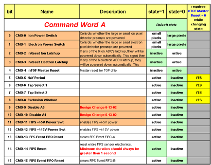
The integer value of
the 15-bit Command word A. Description of command word A shown below:
- CMD_WORD_B
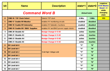
The
integer value of the 15-bit Command word B. Description of Command Word B shown
below:
- EVENT_PARAM_A
- EVENT_PARAM_B
The integer
value of the 15-bit Event parameter B mirror. This parameter contains two 3-bit code
fields that programmably selects the delay taps for energy Fast signals.
Description shown below:
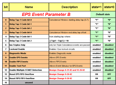
- EVENT_PARAM_C
The integer
value of the 15-bit Event parameter C mirror. This parameter contains one 7-bit field
that programmably selects the number of EPS electron events to be discarded per
electron event that is placed in the Event FIFO buffer.
- HVPS_CLOCK_ADJUST
- BIAS_CLOCK_ADJUST
- LVPS_CONTROL_WORD
- INVALID_CH_ID_COUNT
- EPS_FIFO_RESET_COUNT
EPS-fifo-reset count.
- I2C_BUS_ERR_COUNT
I2C Bus error count. Accumulation period is N1.
- BUS_READ_VALUE
Value provided by most recent
bus read command.
- SPARE
Spare column, unused.
The following are the fields as
defined by the EPSMED.FMT structure file. This file defines the binary table
containing the EPS Medium Priority spectra data. Archive volume is optimized by
defining the table structure once and providing a reference to it in the PDS
label file. The fields are numbered according to their column order in the
table. Data_Type refers to the PDS standards data type for a particular column
in the table.
The FSW6 upload was done on
8/18/2008 and implemented on 8/19/2008. The software update retired the EPS
Medium Priority Spectra packet. Thus there are no EPS Medium Priority EDRs on
or after 8/19/2008.
Table 15 EPSMED.FMT
fields
|
Start
Byte
|
Length
(bytes)
|
Data Type
|
Column Name
|
Summary (see full text for
column description)
|
|
1
|
4
|
MSB Unsigned Integer
|
MET
|
Mission Elapsed Time in seconds.
|
|
5
|
4 X 12
|
MSB Unsigned Integer
|
HI_ION_HISTOGRAM_0
|
12 bin high energy ion histogram for
ion direction 0.
|
|
53
|
4 X 12
|
MSB Unsigned Integer
|
HI_ION_HISTOGRAM_1
|
12 bin high energy ion histogram for
ion direction 1.
|
|
101
|
4 X 12
|
MSB Unsigned Integer
|
HI_ION_HISTOGRAM_2
|
12 bin high energy ion histogram for
ion direction 2.
|
|
149
|
4 X 12
|
MSB Unsigned Integer
|
HI_ION_HISTOGRAM_3
|
12 bin high energy ion histogram for
ion direction 3.
|
|
197
|
4 X 12
|
MSB Unsigned Integer
|
HI_ION_HISTOGRAM_4
|
12 bin high energy ion histogram for
ion direction 4.
|
|
245
|
4 X 12
|
MSB Unsigned Integer
|
HI_ION_HISTOGRAM_5
|
12 bin high energy ion histogram for
ion direction 5.
|
|
293
|
4 X 8
|
MSB Unsigned Integer
|
COARSE_E_HISTOGRAM_0
|
8 bin coarse electron histogram for
electron direction 0.
|
|
325
|
4 X 8
|
MSB Unsigned Integer
|
COARSE_E_HISTOGRAM_1
|
8 bin coarse electron histogram for
electron direction 1.
|
|
357
|
4 X 8
|
MSB Unsigned Integer
|
COARSE_E_HISTOGRAM_2
|
8 bin coarse electron histogram for
electron direction 2.
|
|
389
|
4 X 8
|
MSB Unsigned Integer
|
COARSE_E_HISTOGRAM_3
|
8 bin coarse electron histogram for
electron direction 3.
|
|
421
|
4 X 8
|
MSB Unsigned Integer
|
COARSE_E_HISTOGRAM_4
|
8 bin coarse electron histogram for electron
direction 4.
|
|
453
|
4 X 8
|
MSB Unsigned Integer
|
COARSE_E_HISTOGRAM_5
|
8 bin coarse electron histogram for
electron direction 5.
|
|
485
|
4 X 20
|
MSB Unsigned Integer
|
FINE_E_0
|
20 element array of super bin counts
for electron direction 0.
|
|
565
|
4 X 20
|
MSB Unsigned Integer
|
FINE_E_1
|
20 element array of super bin counts
for electron direction 1.
|
|
645
|
4 X 20
|
MSB Unsigned Integer
|
FINE_E_2
|
20 element array of super bin counts
for electron direction 2.
|
|
725
|
4 X 20
|
MSB Unsigned Integer
|
FINE_E_3
|
20 element array of super bin counts
for electron direction 3.
|
|
805
|
4 X 20
|
MSB Unsigned Integer
|
FINE_E_4
|
20 element array of super bin counts
for electron direction 4.
|
|
885
|
4 X 20
|
MSB Unsigned Integer
|
FINE_E_5
|
20 element array of super bin counts
for electron direction 5.
|
|
965
|
4 X 8
|
MSB Unsigned Integer
|
LOW_ION_HISTOGRAM_0
|
8 bin low energy ion histogram for ion
microchannel plate anode 0.
|
|
997
|
4 X 8
|
MSB Unsigned Integer
|
LOW_ION_HISTOGRAM_1
|
8 bin low energy ion histogram for ion
microchannel plate anode 1.
|
|
1029
|
4 X 8
|
MSB Unsigned Integer
|
LOW_ION_HISTOGRAM_2
|
8 bin low energy ion histogram for ion
microchannel plate anode 2.
|
|
1061
|
4 X 8
|
MSB Unsigned Integer
|
LOW_ION_HISTOGRAM_3
|
8 bin low energy ion histogram for ion
microchannel plate anode 3.
|
|
1093
|
4 X 8
|
MSB Unsigned Integer
|
LOW_ION_HISTOGRAM_4
|
8 bin low energy ion histogram for ion
microchannel plate anode 4.
|
|
1125
|
4 X 8
|
MSB Unsigned Integer
|
LOW_ION_HISTOGRAM_5
|
8 bin low energy ion histogram for ion
microchannel plate anode 5.
|
|
1157
|
4
|
MSB Unsigned Integer
|
HW_COUNT_0
|
One of 17 hardware counters.
|
|
1161
|
4
|
MSB Unsigned Integer
|
HW_COUNT_1
|
One of 17 hardware counters.
|
|
1165
|
4
|
MSB Unsigned Integer
|
HW_COUNT_2
|
One of 17 hardware counters.
|
|
1169
|
4
|
MSB Unsigned Integer
|
HW_COUNT_3
|
One of 17 hardware counters.
|
|
1173
|
4
|
MSB Unsigned Integer
|
HW_COUNT_4
|
One of 17 hardware counters.
|
|
1177
|
4
|
MSB Unsigned Integer
|
HW_COUNT_5
|
One of 17 hardware counters.
|
|
1181
|
4
|
MSB Unsigned Integer
|
HW_COUNT_6
|
One of 17 hardware counters.
|
|
1185
|
4
|
MSB Unsigned Integer
|
HW_COUNT_7
|
One of 17 hardware counters.
|
|
1189
|
4
|
MSB Unsigned Integer
|
HW_COUNT_8
|
One of 17 hardware counters.
|
|
1193
|
4
|
MSB Unsigned Integer
|
HW_COUNT_9
|
One of 17 hardware counters.
|
|
1197
|
4
|
MSB Unsigned Integer
|
HW_COUNT_10
|
One of 17 hardware counters.
|
|
1201
|
4
|
MSB Unsigned Integer
|
HW_COUNT_11
|
One of 17 hardware counters.
|
|
1205
|
4
|
MSB Unsigned Integer
|
HW_COUNT_12
|
One of 17 hardware counters.
|
|
1209
|
4
|
MSB Unsigned Integer
|
HW_COUNT_13
|
One of 17 hardware counters.
|
|
1213
|
4
|
MSB Unsigned Integer
|
HW_COUNT_14
|
One of 17 hardware counters.
|
|
1217
|
4
|
MSB Unsigned Integer
|
HW_COUNT_15
|
One of 17 hardware counters.
|
|
1221
|
4
|
MSB Unsigned Integer
|
HW_COUNT_16
|
One of 17 hardware counters.
|
|
1225
|
4
|
MSB Unsigned Integer
|
E_PROCESSED_COUNT
|
Number of electron events processed.
|
|
1229
|
4
|
MSB Unsigned Integer
|
HI_ION_PROCESSED_COUNT
|
Number of high energy ion events
processed
|
|
1233
|
4
|
MSB Unsigned Integer
|
LO_ION_PROCESSED_COUNT
|
Number of low energy ion events
processed.
|
|
1237
|
4
|
MSB Unsigned Integer
|
PILEUP_E_DISCARD
|
Number of electron events discarded
due to pileup condition.
|
|
1241
|
4
|
MSB Unsigned Integer
|
MULTIPLE_E_DISCARD
|
Number of electron events discarded
due to multiple hits.
|
|
1245
|
4
|
MSB Unsigned Integer
|
PILEUP_ION_DISCARD
|
Number of high energy ion events
discarded due to pileup condition.
|
|
1249
|
4
|
MSB Unsigned Integer
|
MULTIPLE_HI_E_DISCARD
|
Number of high energy ion events
discarded due to multiple hits.
|
- MET
Mission elapsed time, in
seconds at the end of the accumulation.
- HI_ION_HISTOGRAM_0
High energy ion histogram for ion direction 0 (SSD detector 1),
which is 1 of the 6 ion solid state detectors (0 through 5) that define the
entire 160 degree field of view of the sensor for high energy ions, and each
representing about 27 degrees out of the entire field of view (Section
5.2). This channel is accumulated
over a time interval equal to N2 seconds, where N2 is nominally 30 seconds, but
can be changed via command. Histogram contains 12 of the 22 bins shown in Table
4, where the choice of bins is made via ground command. In diagnostic mode the
first 8 items are ion energy spectral bins, as shown in Table 5, and the rest
are zeros.
- HI_ION_HISTOGRAM_1
High energy ion histogram for ion direction 1 (SSD detector 3),
which is 1 of the 6 ion solid state detectors (0 through 5) that define the
entire 160 degree field of view of the sensor for high energy ions, and each
representing about 27 degrees out of the entire field of view (Section
5.2). This channel is accumulated
over a time interval equal to N2 seconds, where N2 is nominally 30 seconds, but
can be changed via command. Histogram contains 12 of the 22 bins shown in Table
4, where the choice of bins is made via ground command. In diagnostic mode the
first 8 items are ion energy spectral bins, as shown in Table 5, and the rest
are zeros.
- HI_ION_HISTOGRAM_2
High energy ion histogram for ion direction 2 (SSD detector 5),
which is 1 of the 6 ion solid state detectors (0 through 5) that define the
entire 160 degree field of view of the sensor for high energy ions, and each
representing about 27 degrees out of the entire field of view (Section 5.2). This channel is accumulated over a time
interval equal to N2 seconds, where N2 is nominally 30 seconds, but can be
changed via command. Histogram contains 12 of the 22 bins shown in Table 4,
where the choice of bins is made via ground command. In diagnostic mode the first
8 items are ion energy spectral bins, as shown in Table 5, and the rest are
zeros.
- HI_ION_HISTOGRAM_3
High energy ion histogram for ion direction 3 (SSD detector 7),
which is 1 of the 6 ion solid state detectors (0 through 5) that define the
entire 160 degree field of view of the sensor for high energy ions, and each
representing about 27 degrees out of the entire field of view (Section
5.2). This channel is accumulated
over a time interval equal to N2 seconds, where N2 is nominally 30 seconds, but
can be changed via command. Histogram contains 12 of the 22 bins shown in Table
4, where the choice of bins is made via ground command. In diagnostic mode the
first 8 items are ion energy spectral bins, as shown in Table 5, and the rest
are zeros.
- HI_ION_HISTOGRAM_4
High energy ion histogram for ion direction 4 (SSD detector 9),
which is 1 of the 6 ion solid state detectors (0 through 5) that define the
entire 160 degree field of view of the sensor for high energy ions, and each
representing about 27 degrees out of the entire field of view (Section
5.2). This channel is accumulated
over a time interval equal to N2 seconds, where N2 is nominally 30 seconds, but
can be changed via command. Histogram contains 12 of the 22 bins shown in Table
4, where the choice of bins is made via ground command. In diagnostic mode the
first 8 items are ion energy spectral bins, as shown in Table 5, and the rest
are zeros.
- HI_ION_HISTOGRAM_5
High energy ion histogram for ion direction 5 (SSD detector 11),
which is 1 of the 6 ion solid state detectors (0 through 5) that define the
entire 160 degree field of view of the sensor for high energy ions, and each
representing about 27 degrees out of the entire field of view (Section
5.2). This channel is accumulated
over a time interval equal to N2 seconds, where N2 is nominally 30 seconds, but
can be changed via command. Histogram contains 12 of the 22 bins shown in Table
4, where the choice of bins is made via ground command. In diagnostic mode the
first 8 items are ion energy spectral bins, as shown in Table 5, and the rest
are zeros.
- COARSE_E_HISTOGRAM_0
Electron histogram for
electron direction 0 (SSD detector 0), which is 1 of the 6 electron solid-state
detectors (numbered 0 through 5) that define the entire 160 degree field of view
of the sensor, and each representing about 27 degrees out of the entire field
of view (Section 5.2). This
channel is accumulated over a time interval of N2 seconds, where N2 is
nominally 30 s but set by ground command. Histogram contains the 8 bins shown
in Table 2.
- COARSE_E_HISTOGRAM_1
Electron histogram for
electron direction 1 (SSD detector 2), which is 1 of the 6 electron solid-state
detectors (numbered 0 through 5) that define the entire 160 degree field of
view of the sensor, and each representing about 27 degrees out of the entire
field of view (Section 5.2).
This channel is accumulated over a time interval of N2 seconds, where N2
is nominally 30 s but set by ground command. Histogram contains the 8 bins
shown in Table 2.
- COARSE_E_ HISTOGRAM_2
Electron histogram for
electron direction 2 (SSD detector 4), which is 1 of the 6 electron solid-state
detectors (numbered 0 through 5) that define the entire 160 degree field of
view of the sensor, and each representing about 27 degrees out of the entire
field of view (Section 5.2).
This channel is accumulated over a time interval of N2 seconds, where N2
is nominally 30 s but set by ground command. Histogram contains the 8 bins
shown in Table 2.
- COARSE_E_ HISTOGRAM_3
Electron histogram for
electron direction 3 (SSD detector 6), which is 1 of the 6 electron solid-state
detectors (numbered 0 through 5) that define the entire 160 degree field of
view of the sensor, and each representing about 27 degrees out of the entire
field of view (Section 5.2).
This channel is accumulated over a time interval of N2 seconds, where N2
is nominally 30 s but set by ground command. Histogram contains the 8 bins
shown in Table 2.
- COARSE_E_ HISTOGRAM_4
Electron histogram for
electron direction 4 (SSD detector 8), which is 1 of the 6 electron solid-state
detectors (numbered 0 through 5) that define the entire 160 degree field of
view of the sensor, and each representing about 27 degrees out of the entire
field of view (Section 5.2).
This channel is accumulated over a time interval of N2 seconds, where N2
is nominally 30 s but set by ground command. Histogram contains the 8 bins
shown in Table 2.
- COARSE_E_ HISTOGRAM_5
Electron histogram for
electron direction 5 (SSD detector 10), which is 1 of the 6 electron
solid-state detectors (numbered 0 through 5) that define the entire 160 degree
field of view of the sensor, and each representing about 27 degrees out of the
entire field of view (Section 5.2).
This channel is accumulated over a time interval of N2 seconds, where N2
is nominally 30 s but set by ground command. Histogram contains the 8 bins
shown in Table 2.
- FINE_E_0
A series of “2 super bin
counts” for electron direction 0 (SSD detector 0), which is 1 of the 6 electron
solid-state detectors (numbered 0 through 5) that define the entire 160 degree
field of view of the sensor, and each representing about 27 degrees out of the
entire field of view (Section 5.2).
Each super bin is the accumulation of a subset of bin counts in one
N2/10 second subinterval. Super bin 0 is the sum of the energy bins 0-3 shown
in Table 2. Super bin 1 is the sum of bins 4-7 shown in Table 2. Each super bin
pair is measured once per subinterval for 10 subintervals, making a total of 20
items.
- FINE_E_1
A series of “2 super bin counts” for electron direction 1 (SSD
detector 2), which is 1 of the 6 electron
solid-state detectors (numbered 0 through 5) that define the entire 160
degree field of view of the sensor, and each representing about 27 degrees out
of the entire field of view (Section 5.2). Each super bin is the accumulation of a subset of bin counts in one N2/10 second
subinterval. Super bin 0 is the sum of the energy bins 0-3 shown in Table 2.
Super bin 1 is the sum of bins 4-7 shown in Table 2. Each super bin pair is
measured once per subinterval for 10 subintervals, making a total of 20 items.
- FINE_E_2
A series of “2 super bin counts” for electron direction 2 (SSD
detector 4), which is 1 of the 6 electron
solid-state detectors (numbered 0 through 5) that define the entire 160
degree field of view of the sensor, and each representing about 27 degrees out
of the entire field of view (Section 5.2).
Each super bin is the accumulation of a subset of bin counts in one
N2/10 second subinterval. Super bin 0 is the sum of the energy bins 0-3 shown
in Table 2. Super bin 1 is the sum of bins 4-7 shown in Table 2. Each super bin
pair is measured once per subinterval for 10 subintervals, making a total of 20
items.
- FINE_E_3
A series of “2 super bin counts” for electron direction 3 (SSD
detector 6), which is 1 of the 6 electron solid-state
detectors (numbered 0 through 5) that define the entire 160 degree field of
view of the sensor, and each representing about 27 degrees out of the entire
field of view (Section 5.2). Each
super bin is the accumulation of a subset of bin counts in one N2/10 second
subinterval. Super bin 0 is the sum of the energy bins 0-3 shown in Table 2.
Super bin 1 is the sum of bins 4-7 shown in Table 2. Each super bin pair is
measured once per subinterval for 10 subintervals, making a total of 20 items.
- FINE_E_4
A series of “2 super bin counts” for electron direction 4 (SSD
detector 8), which is 1 of the 6 electron
solid-state detectors (numbered 0 through 5) that define the entire 160
degree field of view of the sensor, and each representing about 27 degrees out
of the entire field of view (Section 5.2).
Each super bin is the accumulation of a
subset of bin counts in one N2/10 second subinterval. Super bin 0 is the sum of the
energy bins 0-3 shown in Table 2. Super bin 1 is the sum of bins 4-7 shown in
Table 2. Each super bin pair is measured once per subinterval for 10
subintervals, making a total of 20 items.
- FINE_E_5
A series of “2 super bin counts” for electron direction 5 (SSD
detector 10), which is 1 of the 6 electron solid-state detectors (numbered 0
through 5) that define the entire 160 degree field of view of the sensor, and
each representing about 27 degrees out of the entire field of view (Section
5.2). Each super bin is the
accumulation of a subset of bin counts in one N2/10 second subinterval. Super
bin 0 is the sum of the energy bins 0-3 shown in Table 2. Super bin 1 is the
sum of bins 4-7 shown in Table 2. Each super bin pair is measured once per
subinterval for 10 subintervals, making a total of 20 items.
- LOW_ION_ HISTOGRAM_0
Low energy ion histogram for
ion microchannel plate (MCP) anode 0, which is 1 of the 6 ion anodes (numbered
0 through 5) that read charge coming from the MCP sensor and that define the
entire 160 degree field of view of the sensor for low energy ions, and each
representing about 27 degrees out of the entire field of view (Recall that the
Low Energy Ion directionality numbering is switched from that used for high
energy ions; Section 5.2). This
channel is accumulated over a time interval equal to N2 seconds, where N2
nominally 30 seconds but set via command.
Histogram contains the 8 of the 16 bins shown in Table 3, with the
choice of bins set by ground command. In diagnostic mode these items read zero.
- LOW_ION_ HISTOGRAM_1
Low energy ion histogram for
ion microchannel plate (MCP) anode 1, which is 1 of the 6 ion anodes (numbered
0 through 5) that read charge coming from the MCP sensor and that define the
entire 160 degree field of view of the sensor for low energy ions, and each
representing about 27 degrees out of the entire field of view (Recall that the
Low Energy Ion directionality numbering is switched from that used for high
energy ions; Section 5.2). This
channel is accumulated over a time interval equal to N2 seconds, where N2
nominally 30 seconds but set via command.
Histogram contains the 8 of the 16 bins shown in Table 3, with the
choice of bins set by ground command. In diagnostic mode these items read zero.
- LOW_ION_ HISTOGRAM_2
Low energy ion histogram for
ion microchannel plate (MCP) anode 2, which is 1 of the 6 ion anodes (numbered
0 through 5) that read charge coming from the MCP sensor and that define the
entire 160 degree field of view of the sensor for low energy ions, and each
representing about 27 degrees out of the entire field of view (Recall that the
Low Energy Ion directionality numbering is switched from that used for high
energy ions; Section 5.2). This
channel is accumulated over a time interval equal to N2 seconds, where N2
nominally 30 seconds but set via command.
Histogram contains the 8 of the 16 bins shown in Table 3, with the
choice of bins set by ground command. In diagnostic mode these items read zero.
- LOW_ION_ HISTOGRAM_3
Low energy ion histogram for
ion microchannel plate (MCP) anode 3, which is 1 of the 6 ion anodes (numbered
0 through 5) that read charge coming from the MCP sensor and that define the
entire 160 degree field of view of the sensor for low energy ions, and each
representing about 27 degrees out of the entire field of view (Recall that the
Low Energy Ion directionality numbering is switched from that used for high
energy ions; Section 5.2). This
channel is accumulated over a time interval equal to N2 seconds, where N2
nominally 30 seconds but set via command.
Histogram contains the 8 of the 16 bins shown in Table 3, with the
choice of bins set by ground command. In diagnostic mode these items read zero.
- LOW_ION_ HISTOGRAM_4
Low energy ion histogram for
ion microchannel plate (MCP) anode 4, which is 1 of the 6 ion anodes (numbered
0 through 5) that read charge coming from the MCP sensor and that define the
entire 160 degree field of view of the sensor for low energy ions, and each
representing about 27 degrees out of the entire field of view (Recall that the
Low Energy Ion directionality numbering is switched from that used for high
energy ions; Section 5.2). This
channel is accumulated over a time interval equal to N2 seconds, where N2
nominally 30 seconds but set via command.
Histogram contains the 8 of the 16 bins shown in Table 3, with the
choice of bins set by ground command. In diagnostic mode these items read zero.
- LOW_ION_ HISTOGRAM_5
Low energy ion histogram for
ion microchannel plate (MCP) anode 5, which is 1 of the 6 ion anodes (numbered
0 through 5) that read charge coming from the MCP sensor and that define the
entire 160 degree field of view of the sensor for low energy ions, and each
representing about 27 degrees out of the entire field of view (Recall that the
Low Energy Ion directionality numbering is switched from that used for high
energy ions; Section 5.2). This
channel is accumulated over a time interval equal to N2 seconds, where N2
nominally 30 seconds but set via command.
Histogram contains the 8 of the 16 bins shown in Table 3, with the
choice of bins set by ground command. In diagnostic mode these items read zero.
- HW_COUNT_0
One
of 17 hardware counters selected by ground command out of a menu of 35 (All 35
are reported with high priority data: See EPSHIGH.FMT items 26 through
60). . Nominally this item will
contain values for Shaped_0 counter (EPSHIGH.FMT item 38). Here the counters are accumulated over
N2 seconds. An ERRATA file will be
provided should the choice for this item be changed.
- HW_COUNT_1
One
of 17 hardware counters selected by ground command out of a menu of 35 (All 35
are reported with high priority data: See EPSHIGH.FMT items 26 through
60). . Nominally this item will
contain values for Shaped_1 counter (EPSHIGH.FMT item 39). Here the counters are accumulated over
N2 seconds. An ERRATA file will be
provided should the choice for this item be changed.
- HW_COUNT_2
One
of 17 hardware counters selected by ground command out of a menu of 35 (All 35
are reported with high priority data: See EPSHIGH.FMT items 26 through
60). . Nominally this item will contain
values for Shaped_2 counter (EPSHIGH.FMT item 40). Here the counters are accumulated over
N2 seconds. An ERRATA file will be
provided should the choice for this item be changed.
- HW_COUNT_3
One
of 17 hardware counters selected by ground command out of a menu of 35 (All 35
are reported with high priority data: See EPSHIGH.FMT items 26 through
60). . Nominally this item will
contain values for Shaped_3 counter (EPSHIGH.FMT item 41). Here the counters are accumulated over
N2 seconds. An ERRATA file will be
provided should the choice for this item be changed.
- HW_COUNT_4
One
of 17 hardware counters selected by ground command out of a menu of 35 (All 35
are reported with high priority data: See EPSHIGH.FMT items 26 through
60). . Nominally this item will
contain values for Shaped_4 counter (EPSHIGH.FMT item 42). Here the counters are accumulated over
N2 seconds. An ERRATA file will be
provided should the choice for this item be changed.
- HW_COUNT_5
One
of 17 hardware counters selected by ground command out of a menu of 35 (All 35
are reported with high priority data: See EPSHIGH.FMT items 26 through
60). . Nominally this item will
contain values for Shaped_5 counter (EPSHIGH.FMT item 44). Here the counters are accumulated over
N2 seconds. An ERRATA file will be
provided should the choice for this item be changed.
- HW_COUNT_6
One
of 17 hardware counters selected by ground command out of a menu of 35 (All 35
are reported with high priority data: See EPSHIGH.FMT items 26 through
60). . Nominally this item will
contain values for Shaped_6 counter (EPSHIGH.FMT item 45). Here the counters are accumulated over
N2 seconds. An ERRATA file will be
provided should the choice for this item be changed.
- HW_COUNT_7
One
of 17 hardware counters selected by ground command out of a menu of 35 (All 35
are reported with high priority data: See EPSHIGH.FMT items 26 through
60). . Nominally this item will
contain values for Shaped_7 counter (EPSHIGH.FMT item 46). Here the counters are accumulated over
N2 seconds. An ERRATA file will be
provided should the choice for this item be changed.
- HW_COUNT_8
One
of 17 hardware counters selected by ground command out of a menu of 35 (All 35
are reported with high priority data: See EPSHIGH.FMT items 26 through
60). . Nominally this item will
contain values for Shaped_8 counter (EPSHIGH.FMT item 47). Here the counters are accumulated over
N2 seconds. An ERRATA file will be
provided should the choice for this item be changed.
- HW_COUNT_9
One
of 17 hardware counters selected by ground command out of a menu of 35 (All 35
are reported with high priority data: See EPSHIGH.FMT items 26 through
60). . Nominally this item will
contain values for Shaped_9 counter (EPSHIGH.FMT item 48). Here the counters are accumulated over
N2 seconds. An ERRATA file will be
provided should the choice for this item be changed.
- HW_COUNT_10
One
of 17 hardware counters selected by ground command out of a menu of 35 (All 35
are reported with high priority data: See EPSHIGH.FMT items 26 through
60). . Nominally this item will
contain values for Shaped_10 counter (EPSHIGH.FMT item 49). Here the counters are accumulated over
N2 seconds. An ERRATA file will be
provided should the choice for this item be changed.
- HW_COUNT_11
One
of 17 hardware counters selected by ground command out of a menu of 35 (All 35
are reported with high priority data: See EPSHIGH.FMT items 26 through
60). . Nominally this item will
contain values for Shaped_11 counter (EPSHIGH.FMT item 50). Here the counters are accumulated over
N2 seconds. An ERRATA file will be
provided should the choice for this item be changed.
- HW_COUNT_12
One
of 17 hardware counters selected by ground command out of a menu of 35 (All 35
are reported with high priority data: See EPSHIGH.FMT items 26 through
60). . Nominally this item will
contain values for E_EVT_RT counter (EPSHIGH.FMT item 56). Here the counters are accumulated over
N2 seconds. An ERRATA file will be
provided should the choice for this item be changed.
- HW_COUNT_13
One
of 17 hardware counters selected by ground command out of a menu of 35 (All 35
are reported with high priority data: See EPSHIGH.FMT items 26 through
60). . Nominally this item will
contain values for ION_EVT_RT counter (EPSHIGH.FMT item 57). Here the counters are accumulated over
N2 seconds. An ERRATA file will be
provided should the choice for this item be changed.
- HW_COUNT_14
One
of 17 hardware counters selected by ground command out of a menu of 35 (All 35
are reported with high priority data: See EPSHIGH.FMT items 26 through
60). . Nominally this item will
contain values for START_RT counter (EPSHIGH.FMT item 58). Here the counters are accumulated over
N2 seconds. An ERRATA file will be
provided should the choice for this item be changed.
- HW_COUNT_15
One
of 17 hardware counters selected by ground command out of a menu of 35 (All 35
are reported with high priority data: See EPSHIGH.FMT items 26 through
60). . Nominally this item will
contain values for STOP_RT counter (EPSHIGH.FMT item 59). Here the counters are accumulated over
N2 seconds. An ERRATA file will be
provided should the choice for this item be changed.
- HW_COUNT_16
One
of 17 hardware counters selected by ground command out of a menu of 35 (All 35
are reported with high priority data: See EPSHIGH.FMT items 26 through
60). . Nominally this item will
contain values for VALID_TOF_RT counter (EPSHIGH.FMT item 60). Here the counters are accumulated over
N2 seconds. An ERRATA file will be
provided should the choice for this item be changed.
- E_PROCESSED_COUNT
- HI_ION_PROCESSED_COUNT
Number of high energy ion events processed by the Event Processing
Computer during the accumulation interval. Accumulation period is N1.
- LO_ION_PROCESSED_COUNT
Number of low energy ion events processed by the Event Processing
Computer during the accumulation interval. Accumulation period is N1.
- PILEUP_E_DISCARD
Number of electron events discarded by the Event Processing
Computer due to pileup condition.
Accumulation period is N1.
- MULTIPLE_E_DISCARD
Number of electron events discarded by the Event Processing
Computer due to multiple hits.
Accumulation period is N1.
- PILEUP_ION_DISCARD
Number of high energy ion
events discarded by the Event Processing Computer due to pileup
conditions. Accumulation period is
N1.
- MULTIPLE_HI_E_DISCARD
Number of high energy ion events discarded by the Event Processing
Computer due to multiple hits.
Accumulation period is N1.
The following are the fields as
defined by the EPS_PHA.FMT structure file. This file defines the binary table
containing the EPS Pulse Height Analysis (PHA) event data. The FSW6 upload
resulted in changing the EPS PHA data format. It was decided to merge the new
format with the previously existing format rather than create an entirely new
EDR.
Prior to FSW6 the EPS PHA data
could be one of four types: Electron PHA event, Low Energy Ion PHA event, High
Energy Ion PHA event, Diagnostic PHA event. After FSW6 there are no separate
event types.
There are some common fields for
the PHA formats pre and post FSW6, however other fields may be unique. Fields
added as a result of FSW6 are INT_TIME, INT_TIME_MULTI, and ENERGY_BIN. The EPS
PHA binary table will contain all the possible fields that may be populatedes
and will include a “Not Applicable” value when appropriate. Archive volume is optimized by defining
the table structure once and providing a reference to it in the PDS label file.
The fields are numbered according to their column order in the table. Data_Type
refers to the PDS standards data type for a particular column in the table.
Table 16 EPS_PHA.FMT
Fields
|
Start
Byte
|
Length
(bytes)
|
Data Type
|
Column Name
|
Summary (see full text for
column description)
|
|
1
|
4
|
MSB Unsigned Integer
|
MET
|
Mission Elapsed Time in seconds.
|
|
5
|
2
|
MSB Unsigned Integer
|
EVENT_ID
|
Identifies PHA event as one of 4
types.
|
|
7
|
2
|
MSB Unsigned Integer
|
INT_TIME
|
Integration time in seconds.
|
|
9
|
2
|
MSB Unsigned Integer
|
INT_TIME_MULTI
|
Integration time multiplier.
|
|
11
|
2
|
MSB Unsigned Integer
|
ENERGY_BIN
|
High resolution energy bin number
computed by the flight software.
|
|
13
|
2
|
MSB Unsigned Integer
|
ION_E_FLAG
|
Identifies event as either electron or
ion.
|
|
15
|
4
|
MSB Unsigned Integer
|
ENERGY_PEAK
|
PHA value corresponding to the
particle energy.
|
|
19
|
4
|
MSB Unsigned Integer
|
ENERGY_BASELINE
|
Baseline against which the particle
energy is measured.
|
|
23
|
4
|
MSB Unsigned Integer
|
TIME_OF_FLIGHT
|
A measure of the particle’s velocity.
|
|
27
|
2
|
MSB Unsigned Integer
|
MULTIPLE_HITS
|
Flag indicating if more than one
detector received a hit.
|
|
29
|
2
|
MSB Unsigned Integer
|
HEAVY_DISC_0
|
Heavy Ion level 0 discriminator level
was triggered.
|
|
31
|
2
|
MSB Unsigned Integer
|
HEAVY_DISC_1
|
Heavy Ion level 1 discriminator level
was triggered.
|
|
33
|
2
|
MSB Unsigned Integer
|
CHANNEL_NUM
|
Indicates the high energy ion or
electron channel.
|
|
35
|
2
|
MSB Unsigned Integer
|
START_SEGMENT
|
Indicates which start anode fired.
|
1.
MET
Mission elapsed time in
seconds at the end of the accumulation. Corresponds to the MET of the original
science packet. Can be used for correlation with the spectra from EPS High
Medium Priority Spectra EDRs.
2.
EVENT_ID
PHA Event Short ID. There are
4 types: Electron, Low Energy Ion, High Energy Ion, and Diagnostic PHAs. ID =1 Low Energy Ion event ,=3 Electron
event, =5 High Energy Ion event, =11 Diagnostic Event. =99 (N/A) for FSW6 data.
3.
INT_TIME
Integration time in seconds.
=0 (NA) for data created prior to FSW6.
4.
INT_TIME_MULTI
Integration time multiplier.
= 0 (NA) for data created prior to FSW6.
5.
ENERGY_BIN
High Resolution energy bin
number computed by the flight software. =99 (NA) for data created prior to
FSW6.
6.
ION_E_FLAG
Identifies event as either
ion or electron. =0 electron, =1 ion.
7.
ENERGY_PEAK
Pulse Height Analysis (PHA)
value corresponding to the particle energy. Energy Peak. =0 (NA) for Low Energy Ion PHA.
8.
ENERGY_BASELINE
Pulse Height Analysis (PHA)
value corresponding to the baseline against which the particle energy is
measured. Energy Baseline. = 0 (NA)
for Low Energy Ion PHA.
9.
TIME_OF_FLIGHT
Pulse Height Analysis (PHA)
value corresponding to the time it takes the particle to pass through the
sensor (a measure of the particle’s velocity). Time of Flight. =0 (NA) for Electron or Diagnostic PHAs
or FSW6 data.
10.
MULTIPLE_HITS
A flag that indicates that
more than one detector received a hit.
= 99 (NA) for Low Energy Ion PHA.
11.
HEAVY_DISC_0
=1 indicates that the pulse
height on the STOP microchannel plate (MCP) anode was large enough to fire the
heavy ion level 0 discriminator level, a level that is higher than the minimal
level set just above the MCP noise. =99 (NA) for Electron or
Diagnostic PHAs or FSW6 data.
12.
HEAVY_DISC_1
=11 indicates that the pulse
height on the STOP microchannel plate (MCP) anode was large enough to fire the
heavy ion level 1 discriminator level, a level that is higher than the minimal
level set just above the MCP noise and higher than the “heavy ion level 0”
level. =99 (NA) for Electron
or Diagnostic PHAs or FSW6 data.
13.
CHANNEL_NUM
Indicates the high energy ion
or electron channel (0 through 5, indicating directionality within the 160
degree sensor field of view; Section 5.2).
= 99 (NA) for Low Energy Ion PHA.
14.
START_SEGMENT
Indicates which START anode
(0 through 5, indicating directionality within the 160 degree sensor field of
view; recall that the Low Energy Ion directionality numbering – anode
number --is switched from that used for high energy ions; Section 5.2). Start segment. =99 (NA) for Electron
PHAs and for the other types of PHAs if none of the start anodes fired, or for
FSW6 data.
The following are the fields as
defined by the EPS_HIRES.FMT structure file. This file defines the binary table
containing the EPS High Resolution Spectra data. This is a new EDR created as a
result of the FSW6 upload.
Table 17 EPS_HIRES.FMT
Fields
|
Start
Byte
|
Length
(bytes)
|
Data Type
|
Column Name
|
Summary (see full text for
column description)
|
|
1
|
4
|
MSB Unsigned Integer
|
MET
|
Time tag in seconds.
|
|
5
|
2
|
MSB Unsigned Integer
|
INT_TIME
|
Integration time in seconds.
|
|
7
|
2
|
MSB Unsigned Integer
|
INT_TIME_MULTI
|
Integration time multiplier.
|
|
9
|
4 X 36
|
MSB Unsigned Integer
|
ION_SPECTRA_0
|
Hi-res ion energy spectra, sector 0.
|
|
153
|
4 X 36
|
MSB Unsigned Integer
|
ION_SPECTRA_1
|
Hi-res ion energy spectra, sector 1.
|
|
297
|
4 X 36
|
MSB Unsigned Integer
|
ION_SPECTRA_2
|
Hi-res ion energy spectra, sector 2.
|
|
441
|
4 X 36
|
MSB Unsigned Integer
|
ION_SPECTRA_3
|
Hi-res ion energy spectra, sector 3.
|
|
585
|
4 X 36
|
MSB Unsigned Integer
|
ION_SPECTRA_4
|
Hi-res ion energy spectra, sector 4.
|
|
729
|
4 X 36
|
MSB Unsigned Integer
|
ION_SPECTRA_5
|
Hi-res ion energy spectra, sector 5.
|
|
873
|
4 X 36
|
MSB Unsigned Integer
|
E_SPECTRA_0
|
Hi-res electron energy spectra, sector
0.
|
|
1017
|
4 X 36
|
MSB Unsigned Integer
|
E_SPECTRA_1
|
Hi-res electron energy spectra, sector
1.
|
|
1161
|
4 X 36
|
MSB Unsigned Integer
|
E_SPECTRA_2
|
Hi-res electron energy spectra, sector
2.
|
|
1305
|
4 X 36
|
MSB Unsigned Integer
|
E_SPECTRA_3
|
Hi-res electron energy spectra, sector
3.
|
|
1449
|
4 X 36
|
MSB Unsigned Integer
|
E_SPECTRA_4
|
Hi-res electron energy spectra, sector
4.
|
|
1593
|
4 X 36
|
MSB Unsigned Integer
|
E_SPECTRA_5
|
Hi-res electron energy spectra, sector
5.
|
1.
MET
Time tag in seconds.
2.
INT_TIME
Integration time in seconds.
3.
INT_TIME_MULTI
Integration time multiplier.
4.
ION_SPECTRA_0
High resolution ion energy
spectra, sector 0.
5.
ION_SPECTRA_1
High resolution ion energy
spectra, sector 1.
6.
ION_SPECTRA_2
High resolution ion energy
spectra, sector 2.
7.
ION_SPECTRA_3
High resolution ion energy
spectra, sector 3.
8.
ION_SPECTRA_4
High resolution ion energy
spectra, sector 4.
9.
ION_SPECTRA_5
High resolution ion energy
spectra, sector 5.
10.
E_SPECTRA_0
High resolution electron
energy spectra, sector 0.
11.
E_SPECTRA_1
High resolution electron
energy spectra, sector 1.
12.
E_SPECTRA_2
High resolution electron
energy spectra, sector 2.
13.
E_SPECTRA_3
High resolution electron
energy spectra, sector 3.
14.
E_SPECTRA_4
High resolution electron
energy spectra, sector 4.
15.
E_SPECTRA_5
High resolution electron
energy spectra, sector 5.
The following are the fields as
defined by the EPS_LORES.FMT structure file. This file defines the binary table
containing the EPS Low Resolution Spectra data. This is a new EDR created as a
result of the FSW6 upload.
Table 18 EPS_LORES.FMT
Fields
|
Start
Byte
|
Length
(bytes)
|
Data Type
|
Column Name
|
Summary (see full text for
column description)
|
|
1
|
4
|
MSB Unsigned Integer
|
MET
|
Time tag in seconds.
|
|
5
|
2
|
MSB Unsigned Integer
|
INT_TIME
|
Integration time in seconds.
|
|
7
|
4 X 12
|
MSB Unsigned Integer
|
ION_SPECTRA_A_0
|
Lo-res ion energy spectra, first int,
sector 0.
|
|
55
|
4 X 12
|
MSB Unsigned Integer
|
ION_SPECTRA_A_1
|
Low-resolution ion energy spectra,
first integration, sector 1.
|
|
103
|
4 X 12
|
MSB Unsigned Integer
|
ION_SPECTRA_A_2
|
Low-resolution ion energy spectra,
first integration, sector 2.
|
|
151
|
4 X 12
|
MSB Unsigned Integer
|
ION_SPECTRA_A_3
|
Low-resolution ion energy spectra,
first integration, sector 3.
|
|
199
|
4 X 12
|
MSB Unsigned Integer
|
ION_SPECTRA_A_4
|
Low-resolution ion energy spectra,
first integration, sector 4.
|
|
247
|
4 X 12
|
MSB Unsigned Integer
|
ION_SPECTRA_A_5
|
Low-resolution ion energy spectra,
first integration, sector 5.
|
|
295
|
4 X 12
|
MSB Unsigned Integer
|
E_SPECTRA_A_0
|
Low-resolution electron energy
spectra, first integration, sector 0.
|
|
343
|
4 X 12
|
MSB Unsigned Integer
|
E_SPECTRA_A_1
|
Low-resolution electron energy
spectra, first integration, sector 1.
|
|
391
|
4 X 12
|
MSB Unsigned Integer
|
E_SPECTRA_A_2
|
Low-resolution electron energy
spectra, first integration, sector 2.
|
|
439
|
4 X 12
|
MSB Unsigned Integer
|
E_SPECTRA_A_3
|
Low-resolution electron energy
spectra, first integration, sector 3.
|
|
487
|
4 X 12
|
MSB Unsigned Integer
|
E_SPECTRA_A_4
|
Low-resolution electron energy
spectra, first integration, sector 4.
|
|
535
|
4 X 12
|
MSB Unsigned Integer
|
E_SPECTRA_A_5
|
Low-resolution electron energy
spectra, first integration, sector 5.
|
|
583
|
4
|
MSB Unsigned Integer
|
HW_FAST_A_0
|
Threshold counts of pole-zero shaping
circuit, first int, sector 0.
|
|
587
|
4
|
MSB Unsigned Integer
|
HW_FAST_A_1
|
Threshold counts of pole-zero shaping
circuit, first int, sector 1.
|
|
591
|
4
|
MSB Unsigned Integer
|
HW_FAST_A_2
|
Threshold counts of pole-zero shaping
circuit, first int, sector 2.
|
|
595
|
4
|
MSB Unsigned Integer
|
HW_FAST_A_3
|
Threshold counts of pole-zero shaping
circuit, first int, sector 3.
|
|
599
|
4
|
MSB Unsigned Integer
|
HW_FAST_A_4
|
Threshold counts of pole-zero shaping
circuit, first int, sector 4.
|
|
603
|
4
|
MSB Unsigned Integer
|
HW_FAST_A_5
|
Threshold counts of pole-zero shaping
circuit, first int, sector 5.
|
|
607
|
4
|
MSB Unsigned Integer
|
HW_FAST_A_6
|
Threshold counts of pole-zero shaping
circuit, first int, sector 6.
|
|
611
|
4
|
MSB Unsigned Integer
|
HW_FAST_A_7
|
Threshold counts of pole-zero shaping
circuit, first int, sector 7.
|
|
615
|
4
|
MSB Unsigned Integer
|
HW_FAST_A_8
|
Threshold counts of pole-zero shaping
circuit, first int, sector 8.
|
|
619
|
4
|
MSB Unsigned Integer
|
HW_FAST_A_9
|
Threshold counts of pole-zero shaping
circuit, first int, sector 9.
|
|
623
|
4
|
MSB Unsigned Integer
|
HW_FAST_A_10
|
Threshold counts of pole-zero shaping
circuit, first int, sector 10.
|
|
627
|
4
|
MSB Unsigned Integer
|
HW_FAST_A_11
|
Threshold counts of pole-zero shaping
circuit, first int, sector 11.
|
|
631
|
4
|
MSB Unsigned Integer
|
HW_SHAPED_A_0
|
Threshold counts of 3 pole Gaussian
shaping circuit, first int, sector 0
|
|
635
|
4
|
MSB Unsigned Integer
|
HW_SHAPED_A_1
|
Threshold counts of 3 pole Gaussian
shaping circuit, first int, sector 1
|
|
639
|
4
|
MSB Unsigned Integer
|
HW_SHAPED_A_2
|
Threshold counts of 3 pole Gaussian
shaping circuit, first int, sector 2
|
|
643
|
4
|
MSB Unsigned Integer
|
HW_SHAPED_A_3
|
Threshold counts of 3 pole Gaussian
shaping circuit, first int, sector 3
|
|
647
|
4
|
MSB Unsigned Integer
|
HW_SHAPED_A_4
|
Threshold counts of 3 pole Gaussian
shaping circuit, first int, sector 4
|
|
651
|
4
|
MSB Unsigned Integer
|
HW_SHAPED_A_5
|
Threshold counts of 3 pole Gaussian
shaping circuit, first int, sector 5
|
|
655
|
4
|
MSB Unsigned
Integer
|
HW_SHAPED_A_6
|
Threshold
counts of 3 pole Gaussian shaping circuit, first int, sector 6
|
|
659
|
4
|
MSB Unsigned Integer
|
HW_SHAPED_A_7
|
Threshold counts of 3 pole Gaussian
shaping circuit, first int, sector 7
|
|
663
|
4
|
MSB Unsigned Integer
|
HW_SHAPED_A_8
|
Threshold counts of 3 pole Gaussian
shaping circuit, first int, sector 8
|
|
667
|
4
|
MSB Unsigned Integer
|
HW_SHAPED_A_9
|
Threshold counts of 3 pole Gaussian
shaping circuit, first int, sector 9
|
|
671
|
4
|
MSB Unsigned Integer
|
HW_SHAPED_A_10
|
Threshold counts of 3 pole Gaussian
shaping circuit, first int, sector 10
|
|
675
|
4
|
MSB Unsigned Integer
|
HW_SHAPED_A_11
|
Threshold counts of 3 pole Gaussian
shaping circuit, first int, sector 11
|
|
679
|
4
|
MSB Unsigned Integer
|
HW_ION_EVT_A
|
Valid ion events, first int.
|
|
683
|
4
|
MSB Unsigned Integer
|
HW_E_EVT_A
|
Valid electron events, first int.
|
|
687
|
4
|
MSB Unsigned Integer
|
SW_ION_PROC_A
|
Ions processed, first integration.
|
|
691
|
4
|
MSB Unsigned Integer
|
SW_E_PROC_A
|
Electrons processed, first int.
|
|
695
|
4
|
MSB Unsigned Integer
|
SW_ION_PILEUP_A
|
Ions rejected due to pileup, first
int.
|
|
699
|
4
|
MSB Unsigned Integer
|
SW_E_PILEUP_A
|
Electrons rejected due to pileup,
first int.
|
|
703
|
4
|
MSB Unsigned Integer
|
SW_ION_REJ_A
|
Ions rejected due to negative energy,
first int.
|
|
707
|
4
|
MSB Unsigned Integer
|
SW_E_REJ_A
|
Electrons rejected due to negative
energy, first int.
|
|
711
|
4
|
MSB Unsigned Integer
|
SW_MULTIHIT_A
|
Ion or electron events rejected due to
multi-hits, first int.
|
|
715
|
4 X 12
|
MSB Unsigned Integer
|
ION_SPECTRA_B_0
|
Low-resolution ion energy spectra, 2nd
integration, sector 0.
|
|
763
|
4 X 12
|
MSB Unsigned Integer
|
ION_SPECTRA_B_1
|
Low-resolution ion energy spectra, 2nd
integration, sector 1.
|
|
811
|
4 X 12
|
MSB Unsigned Integer
|
ION_SPECTRA_B_2
|
Low-resolution ion energy spectra, 2nd
integration, sector 2.
|
|
859
|
4 X 12
|
MSB Unsigned Integer
|
ION_SPECTRA_B_3
|
Low-resolution ion energy spectra, 2nd
integration, sector 3.
|
|
907
|
4 X 12
|
MSB Unsigned Integer
|
ION_SPECTRA_B_4
|
Low-resolution ion energy spectra, 2nd
integration, sector 4.
|
|
955
|
4 X 12
|
MSB Unsigned Integer
|
ION_SPECTRA_B_5
|
Low-resolution ion energy spectra, 2nd
integration, sector 5.
|
|
1003
|
4 X 12
|
MSB Unsigned Integer
|
E_SPECTRA_B_0
|
Low-resolution electron energy
spectra, 2nd integration, sector 0.
|
|
1051
|
4 X 12
|
MSB Unsigned Integer
|
E_SPECTRA_B_1
|
Low-resolution electron energy
spectra, 2nd integration, sector 1.
|
|
1099
|
4 X 12
|
MSB Unsigned Integer
|
E_SPECTRA_B_2
|
Low-resolution electron energy
spectra, 2nd integration, sector 2.
|
|
1147
|
4 X 12
|
MSB Unsigned Integer
|
E_SPECTRA_B_3
|
Low-resolution electron energy
spectra, 2nd integration, sector 3.
|
|
1195
|
4 X 12
|
MSB Unsigned Integer
|
E_SPECTRA_B_4
|
Low-resolution electron energy
spectra, 2nd integration, sector 4.
|
|
1243
|
4 X 12
|
MSB Unsigned Integer
|
E_SPECTRA_B_5
|
Low-resolution electron energy
spectra, 2nd integration, sector 5.
|
|
1291
|
4
|
MSB Unsigned Integer
|
HW_FAST_B_0
|
Threshold counts of pole-zero shaping
circuit, 2nd int, sector 0.
|
|
1295
|
4
|
MSB Unsigned Integer
|
HW_FAST_B_1
|
Threshold counts of pole-zero shaping
circuit, 2nd int, sector 1.
|
|
1299
|
4
|
MSB Unsigned Integer
|
HW_FAST_B_2
|
Threshold counts of pole-zero shaping
circuit, 2nd int, sector 2.
|
|
1303
|
4
|
MSB Unsigned
Integer
|
HW_FAST_B_3
|
Threshold
counts of pole-zero shaping circuit, 2nd int, sector 3.
|
|
1307
|
4
|
MSB Unsigned Integer
|
HW_FAST_B_4
|
Threshold counts of pole-zero shaping
circuit, 2nd int, sector 4.
|
|
1311
|
4
|
MSB Unsigned Integer
|
HW_FAST_B_5
|
Threshold counts of pole-zero shaping
circuit, 2nd int, sector 5.
|
|
1315
|
4
|
MSB Unsigned Integer
|
HW_FAST_B_6
|
Threshold counts of pole-zero shaping
circuit, 2nd int, sector 6.
|
|
1319
|
4
|
MSB Unsigned Integer
|
HW_FAST_B_7
|
Threshold counts of pole-zero shaping
circuit, 2nd int, sector 7.
|
|
1323
|
4
|
MSB Unsigned Integer
|
HW_FAST_B_8
|
Threshold counts of pole-zero shaping
circuit, 2nd int, sector 8.
|
|
1327
|
4
|
MSB Unsigned Integer
|
HW_FAST_B_9
|
Threshold counts of pole-zero shaping
circuit, 2nd int, sector 9.
|
|
1331
|
4
|
MSB Unsigned Integer
|
HW_FAST_B_10
|
Threshold counts of pole-zero shaping
circuit, 2nd int, sector 10.
|
|
1335
|
4
|
MSB Unsigned Integer
|
HW_FAST_B_11
|
Threshold counts of pole-zero shaping
circuit, 2nd int, sector 11.
|
|
1339
|
4
|
MSB Unsigned Integer
|
HW_SHAPED_B_0
|
Threshold counts of 3 pole Gaussian
shaping circuit, 2nd int, sector 0.
|
|
1343
|
4
|
MSB Unsigned Integer
|
HW_SHAPED_B_1
|
Threshold counts of 3 pole Gaussian
shaping circuit, 2nd int, sector 1.
|
|
1347
|
4
|
MSB Unsigned Integer
|
HW_SHAPED_B_2
|
Threshold counts of 3 pole Gaussian
shaping circuit, 2nd int, sector 2.
|
|
1351
|
4
|
MSB Unsigned Integer
|
HW_SHAPED_B_3
|
Threshold counts of 3 pole Gaussian
shaping circuit, 2nd int, sector 3.
|
|
1355
|
4
|
MSB Unsigned Integer
|
HW_SHAPED_B_4
|
Threshold counts of 3 pole Gaussian
shaping circuit, 2nd int, sector 4.
|
|
1359
|
4
|
MSB Unsigned Integer
|
HW_SHAPED_B_5
|
Threshold counts of 3 pole Gaussian
shaping circuit, 2nd int, sector 5.
|
|
1363
|
4
|
MSB Unsigned Integer
|
HW_SHAPED_B_6
|
Threshold counts of 3 pole Gaussian
shaping circuit, 2nd int, sector 6.
|
|
1367
|
4
|
MSB Unsigned Integer
|
HW_SHAPED_B_7
|
Threshold counts of 3 pole Gaussian
shaping circuit, 2nd int, sector 7.
|
|
1371
|
4
|
MSB Unsigned Integer
|
HW_SHAPED_B_8
|
Threshold counts of 3 pole Gaussian
shaping circuit, 2nd int, sector 8.
|
|
1375
|
4
|
MSB Unsigned Integer
|
HW_SHAPED_B_9
|
Threshold counts of 3 pole Gaussian
shaping circuit, 2nd int, sector 9.
|
|
1379
|
4
|
MSB Unsigned Integer
|
HW_SHAPED_B_10
|
Threshold counts of 3 pole Gaussian
shaping circuit, 2nd int, sector 10.
|
|
1383
|
4
|
MSB Unsigned Integer
|
HW_SHAPED_B_11
|
Threshold counts of 3 pole Gaussian
shaping circuit, 2nd int, sector 11.
|
|
1387
|
4
|
MSB Unsigned Integer
|
HW_ION_EVT_B
|
Valid ion events, 2nd int.
|
|
1391
|
4
|
MSB Unsigned Integer
|
HW_E_EVT_B
|
Valid electron events, 2nd int.
|
|
1395
|
4
|
MSB Unsigned Integer
|
SW_ION_PROC_B
|
Ions processed,counter, 2nd int.
|
|
1399
|
4
|
MSB Unsigned Integer
|
SW_E_PROC_B
|
Electrons processed, 2nd int.
|
|
1403
|
4
|
MSB Unsigned Integer
|
SW_ION_PILEUP_B
|
Ions rejected due to pileup, 2nd int.
|
|
1407
|
4
|
MSB Unsigned Integer
|
SW_E_PILEUP_B
|
Electrons rejected due to pileup, 2nd
int.
|
|
1411
|
4
|
MSB Unsigned Integer
|
SW_ION_REJ_B
|
Ions rejected due to negative energy,
2nd int.
|
|
1415
|
4
|
MSB Unsigned Integer
|
SW_E_REJ_B
|
Electrons rejected due to negative
energy, 2nd int.
|
|
1419
|
4
|
MSB Unsigned Integer
|
SW_MULTIHIT_B
|
Ion or electron events rejected due to
multi-hits, 2nd int.
|
1.
MET
Mission elapsed time, in
seconds.
2.
INT_TIME
Integration time in seconds.
3.
ION_SPECTRA_A_0
Low-resolution ion energy
spectra, first integration, sector 0.
4.
ION_SPECTRA_A_1
Low-resolution ion energy spectra, first
integration, sector 1.
5.
ION_SPECTRA_A_2
Low-resolution ion energy spectra, first
integration, sector 2.
6.
ION_SPECTRA_A_3
Low-resolution ion energy spectra, first
integration, sector 3.
7.
ION_SPECTRA_A_4
Low-resolution ion energy spectra, first
integration, sector 4.
8.
ION_SPECTRA_A_5
Low-resolution ion energy spectra, first
integration, sector 5.
9.
E_SPECTRA_A_0
Low- resolution electron
energy spectra, sector 0.
10.
E_SPECTRA_A_1
Low- resolution electron energy spectra,
sector 1.
11.
E_SPECTRA_A_2
Low- resolution electron
energy spectra, sector 2.
12.
E_SPECTRA_A_3
Low- resolution electron
energy spectra, sector 3.
13.
E_SPECTRA_A_4
Low- resolution electron
energy spectra, sector 4.
14.
E_SPECTRA_A_5
Low- resolution electron
energy spectra, sector 5.
15.
HW_FAST_A_0
Counts the firing of a
discriminator when an analog signal exceeds a settable threshold. The
discriminator is connected to the output of the pole-zero shaping circuit.
Sector 0, first integration.
16.
HW_FAST_A_1
Counts the firing of a
discriminator when an analog signal exceeds a settable threshold. The
discriminator is connected to the output of the pole-zero shaping circuit.
Sector 1, first integration.
17.
HW_FAST_A_2
Counts the firing of a discriminator
when an analog signal exceeds a settable threshold. The discriminator is
connected to the output of the pole-zero shaping circuit. Sector 2, first
integration.
18. HW_FAST_A_3
Counts the firing of a
discriminator when an analog signal exceeds a settable threshold. The
discriminator is connected to the output of the pole-zero shaping circuit.
Sector 3, first integration.
19.
HW_FAST_A_4
Counts the firing of a
discriminator when an analog signal exceeds a settable threshold. The
discriminator is connected to the output of the pole-zero shaping circuit.
Sector 4, first integration.
20.
HW_FAST_A_5
Counts the firing of a
discriminator when an analog signal exceeds a settable threshold. The
discriminator is connected to the output of the pole-zero shaping circuit.
Sector 5, first integration.
21.
HW_FAST_A_6
Counts the firing of a
discriminator when an analog signal exceeds a settable threshold. The
discriminator is connected to the output of the pole-zero shaping circuit.
Sector 6, first integration.
22.
HW_FAST_A_7
Counts the firing of a
discriminator when an analog signal exceeds a settable threshold. The
discriminator is connected to the output of the pole-zero shaping circuit.
Sector 7, first integration.
23.
HW_FAST_A_8
Counts the firing of a
discriminator when an analog signal exceeds a settable threshold. The
discriminator is connected to the output of the pole-zero shaping circuit.
Sector 8, first integration.
24.
HW_FAST_A_9
Counts the firing of a
discriminator when an analog signal exceeds a settable threshold. The
discriminator is connected to the output of the pole-zero shaping circuit.
Sector 9, first integration.
25.
HW_FAST_A_10
Counts the firing of a
discriminator when an analog signal exceeds a settable threshold. The
discriminator is connected to the output of the pole-zero shaping circuit.
Sector 10, first integration.
26.
HW_FAST_A_11
Counts the firing of a
discriminator when an analog signal exceeds a settable threshold. The
discriminator is connected to the output of the pole-zero shaping circuit.
Sector 11, first integration.
27.
HW_SHAPED_A_0
Counts the firing of a
discriminator when an analog signal exceeds a settable threshold. The
discriminator is connected to the output of the 3 pole Gaussian shaping
circuit. Sector 0, first integration.
28.
HW_SHAPED_A_1
Counts the firing of a
discriminator when an analog signal exceeds a settable threshold. The
discriminator is connected to the output of the 3 pole Gaussian shaping
circuit. Sector 1, first integration.
29.
HW_SHAPED_A_2
Counts the firing of a
discriminator when an analog signal exceeds a settable threshold. The
discriminator is connected to the output of the 3 pole Gaussian shaping
circuit. Sector 2, first integration.
30.
HW_SHAPED_A_3
Counts the firing of a
discriminator when an analog signal exceeds a settable threshold. The
discriminator is connected to the output of the 3 pole Gaussian shaping
circuit. Sector 3, first integration.
31.
HW_SHAPED_A_4
Counts the firing of a
discriminator when an analog signal exceeds a settable threshold. The
discriminator is connected to the output of the 3 pole Gaussian shaping
circuit. Sector 4, first integration.
32.
HW_SHAPED_A_5
Counts the firing of a
discriminator when an analog signal exceeds a settable threshold. The
discriminator is connected to the output of the 3 pole Gaussian shaping
circuit. Sector 5, first integration.
33.
HW_SHAPED_A_6
Counts the firing of a
discriminator when an analog signal exceeds a settable threshold. The
discriminator is connected to the output of the 3 pole Gaussian shaping
circuit. Sector 6, first integration.
34.
HW_SHAPED_A_7
Counts the firing of a
discriminator when an analog signal exceeds a settable threshold. The
discriminator is connected to the output of the 3 pole Gaussian shaping
circuit. Sector 7, first integration.
35.
HW_SHAPED_A_8
Counts the firing of a
discriminator when an analog signal exceeds a settable threshold. The
discriminator is connected to the output of the 3 pole Gaussian shaping
circuit. Sector 8, first integration.
36.
HW_SHAPED_A_9
Counts the firing of a
discriminator when an analog signal exceeds a settable threshold. The
discriminator is connected to the output of the 3 pole Gaussian shaping
circuit. Sector 9, first integration.
37.
HW_SHAPED_A_10
Counts the firing of a
discriminator when an analog signal exceeds a settable threshold. The
discriminator is connected to the output of the 3 pole Gaussian shaping
circuit. Sector 10, first integration.
38.
HW_SHAPED_A_11
Counts the firing of a
discriminator when an analog signal exceeds a settable threshold. The
discriminator is connected to the output of the 3 pole Gaussian shaping
circuit. Sector 11, first integration.
39.
HW_ION_EVT_A
Counts the occurrence of a
valid ion event, as determined by the Field Programmable Gate Array (FPGA)-
based valid event logic. The event is counted even if the event information
packet is unable to be placed in the First-in, First-out component (FIFO).
First integration.
40.
HW_E_EVT_A
Counts the occurrence of a
valid electron event, as determined by the Field Programmable Gate Array
(FPGA)-based valid event logic. The event is counted even if the event
information packet is unable to be placed in the First-in, First-out component
(FIFO). First integration.
41.
SW_ION_PROC_A
Ions processed; software
counter. First integration.
42.
SW_E_PROC_A
Electrons processed; software
counter. First integration.
43.
SW_ION_PILEUP_A
Ions rejected due to pileup;
software counter. First integration.
44.
SW_E_PILEUP_A
Electrons rejected due to
pileup; software counter. First integration.
45.
SW_ION_REJ_A
Ions rejected due to negative
energy; software counter. First integration.
46.
SW_E_REJ_A
Electrons rejected due to
negative energy; software counter. First integration.
47.
SW_MULTIHIT_A
Ion or electron events
rejected due to multiple hit; software counter. First integration.
48.
ION_SPECTRA_B_0
Low-resolution ion energy
spectra; second integration; sector 0.
49.
ION_SPECTRA_B_1
Low-resolution ion energy
spectra; second integration; sector 1.
50.
ION_SPECTRA_B_2
Low-resolution ion energy
spectra; second integration; sector 2.
51.
ION_SPECTRA_B_3
Low-resolution ion energy
spectra; second integration; sector 3.
52.
ION_SPECTRA_B_4
Low-resolution ion energy
spectra; second integration; sector 4.
53.
ION_SPECTRA_B_5
Low-resolution ion energy
spectra; second integration; sector 5.
54.
E_SPECTRA_B_0
Low-resolution electron
energy spectra; second integration; sector 0.
55.
E_SPECTRA_B_1
Low-resolution electron
energy spectra; second integration; sector 1.
56.
E_SPECTRA_B_2
Low-resolution electron
energy spectra; second integration; sector 2.
57.
E_SPECTRA_B_3
Low-resolution electron
energy spectra; second integration; sector 3.
58.
E_SPECTRA_B_4
Low-resolution electron
energy spectra; second integration; sector 4.
59.
E_SPECTRA_B_5
Low-resolution electron
energy spectra; second integration; sector 5.
60.
HW_FAST_B_0
Counts the firing of a
discriminator when an analog signal exceeds a settable threshold. The
discriminator is connected to the output of the pole-zero shaping circuit.
Sector 0, second integration.
61.
HW_FAST_B_1
Counts the firing of a
discriminator when an analog signal exceeds a settable threshold. The
discriminator is connected to the output of the pole-zero shaping circuit.
Sector 1, second integration.
62.
HW_FAST_B_2
Counts the firing of a
discriminator when an analog signal exceeds a settable threshold. The
discriminator is connected to the output of the pole-zero shaping circuit.
Sector 2, second integration.
63.
HW_FAST_B_3
Counts the firing of a
discriminator when an analog signal exceeds a settable threshold. The
discriminator is connected to the output of the pole-zero shaping circuit.
Sector 3, second integration.
64.
HW_FAST_B_4
Counts the firing of a
discriminator when an analog signal exceeds a settable threshold. The
discriminator is connected to the output of the pole-zero shaping circuit.
Sector 4, second integration.
65.
HW_FAST_B_5
Counts the firing of a
discriminator when an analog signal exceeds a settable threshold. The
discriminator is connected to the output of the pole-zero shaping circuit.
Sector 5, second integration.
66.
HW_FAST_B_6
Counts the firing of a
discriminator when an analog signal exceeds a settable threshold. The
discriminator is connected to the output of the pole-zero shaping circuit.
Sector 6, second integration.
67.
HW_FAST_B_7
Counts the firing of a
discriminator when an analog signal exceeds a settable threshold. The discriminator
is connected to the output of the pole-zero shaping circuit. Sector 7, second
integration.
68.
HW_FAST_B_8
Counts the firing of a
discriminator when an analog signal exceeds a settable threshold. The
discriminator is connected to the output of the pole-zero shaping circuit.
Sector 8, second integration.
69.
HW_FAST_B_9
Counts the firing of a
discriminator when an analog signal exceeds a settable threshold. The
discriminator is connected to the output of the pole-zero shaping circuit.
Sector 9, second integration.
70.
HW_FAST_B_10
Counts the firing of a
discriminator when an analog signal exceeds a settable threshold. The
discriminator is connected to the output of the pole-zero shaping circuit.
Sector 10, second integration.
71.
HW_FAST_B_11
Counts the firing of a
discriminator when an analog signal exceeds a settable threshold. The
discriminator is connected to the output of the pole-zero shaping circuit.
Sector 11, second integration.
72.
HW_SHAPED_B_0
Counts the firing of a
discriminator when an analog signal exceeds a settable threshold. The
discriminator is connected to the output of the 3 pole Gaussian shaping
circuit. Sector 0, second integration.
73.
HW_SHAPED_B_1
Counts the firing of a
discriminator when an analog signal exceeds a settable threshold. The discriminator
is connected to the output of the 3 pole Gaussian shaping circuit. Sector 1,
second integration.
74.
HW_SHAPED_B_2
Counts the firing of a
discriminator when an analog signal exceeds a settable threshold. The
discriminator is connected to the output of the 3 pole Gaussian shaping
circuit. Sector 2, second integration.
75.
HW_SHAPED_B_3
Counts the firing of a
discriminator when an analog signal exceeds a settable threshold. The
discriminator is connected to the output of the 3 pole Gaussian shaping
circuit. Sector 3, second integration.
76.
HW_SHAPED_B_4
Counts the firing of a
discriminator when an analog signal exceeds a settable threshold. The
discriminator is connected to the output of the 3 pole Gaussian shaping
circuit. Sector 4, second integration.
77.
HW_SHAPED_B_5
Counts the firing of a
discriminator when an analog signal exceeds a settable threshold. The
discriminator is connected to the output of the 3 pole Gaussian shaping
circuit. Sector 5, second integration.
78.
HW_SHAPED_B_6
Counts the firing of a discriminator
when an analog signal exceeds a settable threshold. The discriminator is
connected to the output of the 3 pole Gaussian shaping circuit. Sector 6,
second integration.
79.
HW_SHAPED_B_7
Counts the firing of a
discriminator when an analog signal exceeds a settable threshold. The
discriminator is connected to the output of the 3 pole Gaussian shaping
circuit. Sector 7, second integration.
80.
HW_SHAPED_B_8
Counts the firing of a
discriminator when an analog signal exceeds a settable threshold. The
discriminator is connected to the output of the 3 pole Gaussian shaping
circuit. Sector 8, second integration.
81.
HW_SHAPED_B_9
Counts the firing of a
discriminator when an analog signal exceeds a settable threshold. The
discriminator is connected to the output of the 3 pole Gaussian shaping
circuit. Sector 9, second integration.
82.
HW_SHAPED_B_10
Counts the firing of a
discriminator when an analog signal exceeds a settable threshold. The
discriminator is connected to the output of the 3 pole Gaussian shaping
circuit. Sector 10, second integration.
83.
HW_SHAPED_B_11
Counts the firing of a
discriminator when an analog signal exceeds a settable threshold. The
discriminator is connected to the output of the 3 pole Gaussian shaping
circuit. Sector 11, second integration.
84.
HW_ION_EVT_B
Counts the occurrence of a
valid ion event, as determined by the FPGA-based valid event logic. The event
is counted even if the event information packet is unable to be placed in the
FIFO. Second integration.
85.
HW_E_EVT_B
Counts the occurrence of a valid
electron event, as determined by the FPGA-based valid event logic. The event is
counted even if the event information packet is unable to be placed in the
FIFO. Second integration.
86.
SW_ION_PROC_B
Ions processed, software
counter. Second integration.
87.
SW_E_PROC_B
Electrons processed, software
counter. Second integration.
88.
SW_ION_PILEUP_B
Ions rejected due to pileup,
software counter. Second integration.
89.
SW_E_PILEUP_B
Electrons rejected due to
pileup, software counter. Second integration.
90.
SW_ION_REJ_B
Ions rejected due to negative
energy, software counter. Second integration.
91. SW_E_REJ_B
Electrons rejected due to
negative energy, software counter. Second integration.
92.
SW_MULTIHIT_B
Ion or electron events
rejected due to multiple hit, software counter. Second integration.
The following are the fields as
defined by the EPS_SUM.FMT structure file. This file defines the binary table
containing the EPS Summary Spectra data. This is a new EDR created as a result
of the FSW6 upload.
Table 19 EPS_SUM.FMT
Fields
|
Start
Byte
|
Length
(bytes)
|
Data Type
|
Column Name
|
Summary (see full text for
column description)
|
|
1
|
4
|
MSB Unsigned Integer
|
MET
|
Time tag in seconds.
|
|
5
|
2
|
MSB Unsigned Integer
|
INT_TIME
|
Integration time in seconds.
|
|
7
|
2
|
MSB Unsigned Integer
|
INT_TIME_MULTI
|
Integration time multiplier.
|
|
9
|
4 X 12
|
MSB Unsigned Integer
|
ION_SPECTRA_0
|
Lo-res ion energy spectra, sector 0.
|
|
57
|
4 X 12
|
MSB Unsigned Integer
|
ION_SPECTRA_1
|
Lo-res ion energy spectra, sector 1.
|
|
105
|
4 X 12
|
MSB Unsigned Integer
|
ION_SPECTRA_2
|
Lo-res ion energy spectra, sector 2.
|
|
153
|
4 X 12
|
MSB Unsigned Integer
|
ION_SPECTRA_3
|
Lo-res ion energy spectra, sector 3.
|
|
201
|
4 X 12
|
MSB Unsigned Integer
|
ION_SPECTRA_4
|
Lo-res ion energy spectra, sector 4.
|
|
249
|
4 X 12
|
MSB Unsigned Integer
|
ION_SPECTRA_5
|
Lo-res ion energy spectra, sector 5.
|
|
297
|
4 X 12
|
MSB Unsigned Integer
|
E_SPECTRA_0
|
Lo-res electron energy spectra, sector
0.
|
|
345
|
4 X 12
|
MSB Unsigned Integer
|
E_SPECTRA_1
|
Lo-res electron energy spectra, sector
1.
|
|
393
|
4 X 12
|
MSB Unsigned Integer
|
E_SPECTRA_2
|
Lo-res electron energy spectra, sector
2.
|
|
441
|
4 X 12
|
MSB Unsigned Integer
|
E_SPECTRA_3
|
Lo-res electron energy spectra, sector
3.
|
|
489
|
4 X 12
|
MSB Unsigned Integer
|
E_SPECTRA_4
|
Lo-res electron energy spectra, sector
4.
|
|
537
|
4 X 12
|
MSB Unsigned Integer
|
E_SPECTRA_5
|
Lo-res electron energy spectra, sector
5.
|
|
585
|
4
|
MSB Unsigned Integer
|
HW_FAST_0
|
Threshold counts of pole-zero shaping
circuit, sector 1.
|
|
589
|
4
|
MSB Unsigned Integer
|
HW_FAST_1
|
Threshold counts of pole-zero shaping
circuit, sector 2.
|
|
593
|
4
|
MSB Unsigned Integer
|
HW_FAST_2
|
Threshold counts of pole-zero shaping
circuit, sector 3.
|
|
597
|
4
|
MSB Unsigned Integer
|
HW_FAST_3
|
Threshold counts of pole-zero shaping
circuit, sector 4.
|
|
601
|
4
|
MSB Unsigned Integer
|
HW_FAST_4
|
Threshold counts of pole-zero shaping
circuit, sector 5.
|
|
605
|
4
|
MSB Unsigned Integer
|
HW_FAST_5
|
Threshold counts of pole-zero shaping
circuit, sector 6.
|
|
609
|
4
|
MSB Unsigned Integer
|
HW_FAST_6
|
Threshold counts of pole-zero shaping
circuit, sector 7.
|
|
613
|
4
|
MSB Unsigned Integer
|
HW_FAST_7
|
Threshold counts of pole-zero shaping
circuit, sector 8.
|
|
617
|
4
|
MSB Unsigned Integer
|
HW_FAST_8
|
Threshold counts of pole-zero shaping
circuit, sector 9.
|
|
621
|
4
|
MSB Unsigned Integer
|
HW_FAST_9
|
Threshold counts of pole-zero shaping
circuit, sector 10.
|
|
625
|
4
|
MSB Unsigned Integer
|
HW_FAST_10
|
Threshold counts of pole-zero shaping
circuit, sector 10.
|
|
629
|
4
|
MSB Unsigned Integer
|
HW_FAST_11
|
Threshold counts of pole-zero shaping
circuit, sector 11.
|
|
633
|
4
|
MSB Unsigned Integer
|
HW_SHAPED_0
|
Threshold counts of 3 pole Gaussian
shaping circuit, sector 0
|
|
637
|
4
|
MSB Unsigned Integer
|
HW_SHAPED_1
|
Threshold counts of 3 pole Gaussian
shaping circuit, sector 1
|
|
641
|
4
|
MSB Unsigned Integer
|
HW_SHAPED_2
|
Threshold counts of 3 pole Gaussian
shaping circuit, sector 2
|
|
645
|
4
|
MSB Unsigned Integer
|
HW_SHAPED_3
|
Threshold counts of 3 pole Gaussian
shaping circuit, sector 3
|
|
649
|
4
|
MSB Unsigned Integer
|
HW_SHAPED_4
|
Threshold counts of 3 pole Gaussian
shaping circuit, sector 4
|
|
653
|
4
|
MSB Unsigned Integer
|
HW_SHAPED_5
|
Threshold counts of 3 pole Gaussian
shaping circuit, sector 5
|
|
657
|
4
|
MSB Unsigned Integer
|
HW_SHAPED_6
|
Threshold counts of 3 pole Gaussian
shaping circuit, sector 6
|
|
661
|
4
|
MSB Unsigned Integer
|
HW_SHAPED_7
|
Threshold counts of 3 pole Gaussian
shaping circuit, sector 7
|
|
665
|
4
|
MSB Unsigned Integer
|
HW_SHAPED_8
|
Threshold counts of 3 pole Gaussian
shaping circuit, sector 8
|
|
669
|
4
|
MSB Unsigned Integer
|
HW_SHAPED_9
|
Threshold counts of 3 pole Gaussian
shaping circuit, sector 9
|
|
673
|
4
|
MSB Unsigned Integer
|
HW_SHAPED_10
|
Threshold counts of 3 pole Gaussian
shaping circuit, sector 10
|
|
677
|
4
|
MSB Unsigned Integer
|
HW_SHAPED_11
|
Threshold counts of 3 pole Gaussian
shaping circuit, sector 11
|
|
681
|
4
|
MSB Unsigned Integer
|
HW_ION_EVT
|
Valid ion events.
|
|
685
|
4
|
MSB Unsigned Integer
|
HW_E_EVT
|
Valid electron events.
|
|
689
|
4
|
MSB Unsigned Integer
|
SW_ION_PROC
|
Ions processed.
|
|
693
|
4
|
MSB Unsigned Integer
|
SW_E_PROC
|
Electrons processed.
|
|
697
|
4
|
MSB Unsigned Integer
|
SW_ION_PILEUP
|
Ions rejected due to pileup.
|
|
701
|
4
|
MSB Unsigned Integer
|
SW_E_PILEUP
|
Electrons rejected due to pileup.
|
|
705
|
4
|
MSB Unsigned Integer
|
SW_ION_REJ
|
Ions rejected due to negative energy.
|
|
709
|
4
|
MSB Unsigned Integer
|
SW_E_REJ
|
Electrons rejected due to negative
energy.
|
|
713
|
4
|
MSB Unsigned Integer
|
SW_MULTIHIT
|
Ion or electron events rejected due to
multi-hits.
|
1.
MET
Time tag in seconds.
2.
INT_TIME
Integration time in seconds.
3.
INT_TIME_MULTI
Integration time multiplier.
4.
ION_SPECTRA_0
Low-resolution ion energy
spectra, sector 0.
5.
ION_SPECTRA_1
Low-resolution ion energy
spectra, sector 1.
6.
ION_SPECTRA_2
Low-resolution ion energy
spectra, sector 2.
7.
ION_SPECTRA_3
Low-resolution ion energy
spectra, sector 3.
8.
ION_SPECTRA_4
Low-resolution ion energy
spectra, sector 4.
9.
ION_SPECTRA_5
Low-resolution ion energy
spectra, sector 5.
10.
E_SPECTRA_0
Low-resolution electron
energy spectra, sector 0.
11.
E_SPECTRA_1
Low-resolution electron
energy spectra, sector 1.
12.
E_SPECTRA_2
Low-resolution electron
energy spectra, sector 2.
13.
E_SPECTRA_3
Low-resolution electron
energy spectra, sector 3.
14.
E_SPECTRA_4
Low-resolution electron
energy spectra, sector 4.
15.
E_SPECTRA_5
Low-resolution electron
energy spectra, sector 5.
16.
HW_FAST_0
Counts the firing of a
discriminator when an analog signal exceeds a settable threshold. The
discriminator is connected to the output of the pole-zero shaping circuit.
Sector 0.
17.
HW_FAST_1
Counts the firing of a
discriminator when an analog signal exceeds a settable threshold. The
discriminator is connected to the output of the pole-zero shaping circuit.
Sector 1.
18.
HW_FAST_2
Counts the firing of a discriminator
when an analog signal exceeds a settable threshold. The discriminator is
connected to the output of the pole-zero shaping circuit. Sector 2.
19.
HW_FAST_3
Counts the firing of a
discriminator when an analog signal exceeds a settable threshold. The
discriminator is connected to the output of the pole-zero shaping circuit.
Sector 3.
20.
HW_FAST_4
Counts the firing of a
discriminator when an analog signal exceeds a settable threshold. The
discriminator is connected to the output of the pole-zero shaping circuit.
Sector 4.
21.
HW_FAST_5
Counts the firing of a
discriminator when an analog signal exceeds a settable threshold. The
discriminator is connected to the output of the pole-zero shaping circuit.
Sector 5.
22. HW_FAST_6
Counts the firing of a
discriminator when an analog signal exceeds a settable threshold. The
discriminator is connected to the output of the pole-zero shaping circuit.
Sector 6.
23.
HW_FAST_7
Counts the firing of a
discriminator when an analog signal exceeds a settable threshold. The
discriminator is connected to the output of the pole-zero shaping circuit.
Sector 7.
24.
HW_FAST_8
Counts the firing of a
discriminator when an analog signal exceeds a settable threshold. The
discriminator is connected to the output of the pole-zero shaping circuit. Sector
8.
25.
HW_FAST_9
Counts the firing of a
discriminator when an analog signal exceeds a settable threshold. The
discriminator is connected to the output of the pole-zero shaping circuit.
Sector 9.
26.
HW_FAST_10
Counts the firing of a
discriminator when an analog signal exceeds a settable threshold. The
discriminator is connected to the output of the pole-zero shaping circuit.
Sector 10.
27.
HW_FAST_11
Counts the firing of a
discriminator when an analog signal exceeds a settable threshold. The
discriminator is connected to the output of the pole-zero shaping circuit.
Sector 11.
28.
HW_SHAPED_0
Counts the firing of a
discriminator when an analog signal exceeds a settable threshold. The
discriminator is connected to the output of the 3 pole Gaussian shaping
circuit. Sector 0.
29.
HW_SHAPED_1
Counts the firing of a
discriminator when an analog signal exceeds a settable threshold. The
discriminator is connected to the output of the 3 pole Gaussian shaping
circuit. Sector 1.
30.
HW_SHAPED_2
Counts the firing of a
discriminator when an analog signal exceeds a settable threshold. The
discriminator is connected to the output of the 3 pole Gaussian shaping
circuit. Sector 2.
31.
HW_SHAPED_3
Counts the firing of a
discriminator when an analog signal exceeds a settable threshold. The discriminator
is connected to the output of the 3 pole Gaussian shaping circuit. Sector 3.
32.
HW_SHAPED_4
Counts the firing of a
discriminator when an analog signal exceeds a settable threshold. The
discriminator is connected to the output of the 3 pole Gaussian shaping
circuit. Sector 4.
33.
HW_SHAPED_5
Counts the firing of a
discriminator when an analog signal exceeds a settable threshold. The
discriminator is connected to the output of the 3 pole Gaussian shaping
circuit. Sector 5.
34.
HW_SHAPED_6
Counts the firing of a
discriminator when an analog signal exceeds a settable threshold. The
discriminator is connected to the output of the 3 pole Gaussian shaping
circuit. Sector 6.
35.
HW_SHAPED_7
Counts the firing of a
discriminator when an analog signal exceeds a settable threshold. The
discriminator is connected to the output of the 3 pole Gaussian shaping
circuit. Sector 7.
36.
HW_SHAPED_8
Counts the firing of a
discriminator when an analog signal exceeds a settable threshold. The
discriminator is connected to the output of the 3 pole Gaussian shaping
circuit. Sector 8.
37.
HW_SHAPED_9
Counts the firing of a
discriminator when an analog signal exceeds a settable threshold. The
discriminator is connected to the output of the 3 pole Gaussian shaping
circuit. Sector 9.
38.
HW_SHAPED_10
Counts the firing of a
discriminator when an analog signal exceeds a settable threshold. The
discriminator is connected to the output of the 3 pole Gaussian shaping
circuit. Sector 10.
39.
HW_SHAPED_11
Counts the firing of a
discriminator when an analog signal exceeds a settable threshold. The
discriminator is connected to the output of the 3 pole Gaussian shaping
circuit. Sector 11.
40.
HW_ION_EVT
Counts the occurrence of a
valid ion event, as determined by the Field Programmable Gate Array (FPGA)-
based valid event logic. The event is counted even if the event information
packet is unable to be placed in the First-in, First-out component (FIFO).
41.
HW_E_EVT
Counts the occurrence of a
valid electron event, as determined by the Field Programmable Gate Array (FPGA)-based
valid event logic. The event is counted even if the event information packet is
unable to be placed in the FIFO.
42.
SW_ION_PROC
Ions processed; software
counter.
43.
SW_E_PROC
Electrons processed; software
counter.
44.
SW_ION_PILEUP
Ions rejected due to pileup;
software counter.
45.
SW_E_PILEUP_A
Electrons rejected due to
pileup; software counter.
46.
SW_ION_REJ_A
Ions rejected due to negative
energy; software counter.
47.
SW_E_REJ_A
Electrons rejected due to
negative energy; software counter.
48.
SW_MULTIHIT_A
Ion or electron events
rejected due to multiple hit; software counter.
The following are the fields as
defined by the EPS_SCAN.FMT structure file. This file defines the binary table
containing the EPS Scan data. This is a new EDR created as a result of the FSW6
upload.
Table 20 EPS_SCAN.FMT
Fields
|
Start
Byte
|
Length
(bytes)
|
Data Type
|
Column Name
|
Summary (see full text for
column description)
|
|
1
|
4
|
MSB Unsigned Integer
|
MET
|
Time tag in seconds.
|
|
5
|
4
|
MSB Unsigned Integer
|
FAST_A_0
|
Threshold counts of pole-zero shaping
circuit, first threshold, sector 0.
|
|
9
|
4
|
MSB Unsigned Integer
|
FAST_A_1
|
Threshold counts of pole-zero shaping
circuit, first threshold, sector 1.
|
|
13
|
4
|
MSB Unsigned Integer
|
FAST_A_2
|
Threshold counts of pole-zero shaping
circuit, first threshold, sector 2.
|
|
17
|
4
|
MSB Unsigned Integer
|
FAST_A_3
|
Threshold counts of pole-zero shaping
circuit, first threshold, sector 3.
|
|
21
|
4
|
MSB Unsigned Integer
|
FAST_A_4
|
Threshold counts of pole-zero shaping
circuit, first threshold, sector 4.
|
|
25
|
4
|
MSB Unsigned Integer
|
FAST_A_5
|
Threshold counts of pole-zero shaping
circuit, first threshold, sector 5.
|
|
29
|
4
|
MSB Unsigned Integer
|
FAST_A_6
|
Threshold counts of pole-zero shaping
circuit, first threshold, sector 6.
|
|
33
|
4
|
MSB Unsigned Integer
|
FAST_A_7
|
Threshold counts of pole-zero shaping
circuit, first threshold, sector 7.
|
|
37
|
4
|
MSB Unsigned Integer
|
FAST_A_8
|
Threshold counts of pole-zero shaping
circuit, first threshold, sector 8.
|
|
41
|
4
|
MSB Unsigned Integer
|
FAST_A_9
|
Threshold counts of pole-zero shaping
circuit, first threshold, sector 9.
|
|
45
|
4
|
MSB Unsigned Integer
|
FAST_A_10
|
Threshold counts of pole-zero shaping
circuit, first threshold, sector 10.
|
|
49
|
4
|
MSB Unsigned Integer
|
FAST_A_11
|
Threshold counts of pole-zero shaping
circuit, first threshold, sector 11.
|
|
53
|
4
|
MSB Unsigned Integer
|
SHAPED_A_0
|
Threshold counts of 3 pole Gaussian
shaping circuit, first threshold, sector 0.
|
|
57
|
4
|
MSB Unsigned Integer
|
SHAPED_A_1
|
Threshold counts of 3 pole Gaussian
shaping circuit, first threshold, sector 1.
|
|
61
|
4
|
MSB Unsigned Integer
|
SHAPED_A_2
|
Threshold counts of 3 pole Gaussian
shaping circuit, first threshold, sector 2.
|
|
65
|
4
|
MSB Unsigned Integer
|
SHAPED_A_3
|
Threshold counts of 3 pole Gaussian
shaping circuit, first threshold, sector 3.
|
|
69
|
4
|
MSB Unsigned Integer
|
SHAPED_A_4
|
Threshold counts of 3 pole Gaussian
shaping circuit, first threshold, sector 4.
|
|
73
|
4
|
MSB Unsigned Integer
|
SHAPED_A_5
|
Threshold counts of 3 pole Gaussian
shaping circuit, first threshold, sector 5.
|
|
77
|
4
|
MSB Unsigned Integer
|
SHAPED_A_6
|
Threshold counts of 3 pole Gaussian
shaping circuit, first threshold, sector 6.
|
|
81
|
4
|
MSB Unsigned Integer
|
SHAPED_A_7
|
Threshold counts of 3 pole Gaussian
shaping circuit, first threshold, sector 7.
|
|
85
|
4
|
MSB Unsigned Integer
|
SHAPED_A_8
|
Threshold counts of 3 pole Gaussian
shaping circuit, first threshold, sector 8.
|
|
89
|
4
|
MSB Unsigned Integer
|
SHAPED_A_9
|
Threshold counts of 3 pole Gaussian
shaping circuit, first threshold, sector 9.
|
|
93
|
4
|
MSB Unsigned Integer
|
SHAPED_A_10
|
Threshold counts of 3 pole Gaussian shaping
circuit, first threshold, sector 10.
|
|
97
|
4
|
MSB Unsigned Integer
|
SHAPED_A_11
|
Threshold counts of 3 pole Gaussian
shaping circuit, first threshold, sector 11.
|
|
101
|
4
|
MSB Unsigned Integer
|
FAST_B_0
|
Threshold counts of pole-zero shaping
circuit, second threshold, sector 0.
|
|
105
|
4
|
MSB Unsigned Integer
|
FAST_B_1
|
Threshold counts of pole-zero shaping
circuit, second threshold, sector 1.
|
|
109
|
4
|
MSB Unsigned Integer
|
FAST_B_2
|
Threshold counts of pole-zero shaping
circuit, second threshold, sector 2.
|
|
113
|
4
|
MSB Unsigned Integer
|
FAST_B_3
|
Threshold counts of pole-zero shaping
circuit, second threshold, sector 3.
|
|
117
|
4
|
MSB Unsigned Integer
|
FAST_B_4
|
Threshold counts of pole-zero shaping
circuit, second threshold, sector 4.
|
|
121
|
4
|
MSB Unsigned Integer
|
FAST_B_5
|
Threshold counts of pole-zero shaping
circuit, second threshold, sector 5.
|
|
125
|
4
|
MSB Unsigned Integer
|
FAST_B_6
|
Threshold counts of pole-zero shaping
circuit, second threshold, sector 6.
|
|
129
|
4
|
MSB Unsigned Integer
|
FAST_B_7
|
Threshold counts of pole-zero shaping
circuit, second threshold, sector 7.
|
|
133
|
4
|
MSB Unsigned Integer
|
FAST_B_8
|
Threshold counts of pole-zero shaping
circuit, second threshold, sector 8.
|
|
137
|
4
|
MSB Unsigned Integer
|
FAST_B_9
|
Threshold counts of pole-zero shaping
circuit, second threshold, sector 9.
|
|
141
|
4
|
MSB Unsigned Integer
|
FAST_B_10
|
Threshold counts of pole-zero shaping
circuit, second threshold, sector 10.
|
|
145
|
4
|
MSB Unsigned Integer
|
FAST_B_11
|
Threshold counts of pole-zero shaping
circuit, second threshold, sector 11.
|
|
149
|
4
|
MSB Unsigned Integer
|
SHAPED_B_0
|
Threshold counts of 3 pole Gaussian
shaping circuit, second threshold, sector 0.
|
|
153
|
4
|
MSB Unsigned Integer
|
SHAPED_B_1
|
Threshold counts of 3 pole Gaussian
shaping circuit, second threshold, sector 1.
|
|
157
|
4
|
MSB Unsigned Integer
|
SHAPED_B_2
|
Threshold counts of 3 pole Gaussian
shaping circuit, second threshold, sector 2.
|
|
161
|
4
|
MSB Unsigned Integer
|
SHAPED_B_3
|
Threshold counts of 3 pole Gaussian
shaping circuit, second threshold, sector 3.
|
|
165
|
4
|
MSB Unsigned Integer
|
SHAPED_B_4
|
Threshold counts of 3 pole Gaussian
shaping circuit, second threshold, sector 4.
|
|
169
|
4
|
MSB Unsigned Integer
|
SHAPED_B_5
|
Threshold counts of 3 pole Gaussian
shaping circuit, second threshold, sector 5.
|
|
173
|
4
|
MSB Unsigned Integer
|
SHAPED_B_6
|
Threshold counts of 3 pole Gaussian
shaping circuit, second threshold, sector 6.
|
|
177
|
4
|
MSB Unsigned Integer
|
SHAPED_B_7
|
Threshold counts of 3 pole Gaussian
shaping circuit, second threshold, sector 7.
|
|
181
|
4
|
MSB Unsigned Integer
|
SHAPED_B_8
|
Threshold counts of 3 pole Gaussian
shaping circuit, second threshold, sector 8.
|
|
185
|
4
|
MSB Unsigned Integer
|
SHAPED_B_9
|
Threshold counts of 3 pole Gaussian
shaping circuit, second threshold, sector 9.
|
|
189
|
4
|
MSB Unsigned Integer
|
SHAPED_B_10
|
Threshold counts of 3 pole Gaussian
shaping circuit, second threshold, sector 10.
|
|
193
|
4
|
MSB Unsigned Integer
|
SHAPED_B_11
|
Threshold counts of 3 pole Gaussian
shaping circuit, second threshold, sector 11.
|
|
197
|
4
|
MSB Unsigned Integer
|
FAST_C_0
|
Threshold counts of pole-zero shaping
circuit, third threshold, sector 0.
|
|
201
|
4
|
MSB Unsigned Integer
|
FAST_C_1
|
Threshold counts of pole-zero shaping
circuit, third threshold, sector 1.
|
|
205
|
4
|
MSB Unsigned Integer
|
FAST_C_2
|
Threshold counts of pole-zero shaping
circuit, third threshold, sector 2.
|
|
209
|
4
|
MSB Unsigned Integer
|
FAST_C_3
|
Threshold counts of pole-zero shaping
circuit, third threshold, sector 3.
|
|
213
|
4
|
MSB Unsigned Integer
|
FAST_C_4
|
Threshold counts of pole-zero shaping
circuit, third threshold, sector 4.
|
|
217
|
4
|
MSB Unsigned Integer
|
FAST_C_5
|
Threshold counts of pole-zero shaping
circuit, third threshold, sector 5.
|
|
221
|
4
|
MSB Unsigned Integer
|
FAST_C_6
|
Threshold counts of pole-zero shaping
circuit, third threshold, sector 6.
|
|
225
|
4
|
MSB Unsigned Integer
|
FAST_C_7
|
Threshold counts of pole-zero shaping
circuit, third threshold, sector 7.
|
|
229
|
4
|
MSB Unsigned Integer
|
FAST_C_8
|
Threshold counts of pole-zero shaping
circuit, third threshold, sector 8.
|
|
233
|
4
|
MSB Unsigned Integer
|
FAST_C_9
|
Threshold counts of pole-zero shaping
circuit, third threshold, sector 9.
|
|
237
|
4
|
MSB Unsigned Integer
|
FAST_C_10
|
Threshold counts of pole-zero shaping
circuit, third threshold, sector 10.
|
|
241
|
4
|
MSB Unsigned Integer
|
FAST_C_11
|
Threshold counts of pole-zero shaping
circuit, third threshold, sector 11.
|
|
245
|
4
|
MSB Unsigned Integer
|
SHAPED_C_0
|
Threshold counts of 3 pole Gaussian
shaping circuit, third threshold, sector 0.
|
|
249
|
4
|
MSB Unsigned Integer
|
SHAPED_C_1
|
Threshold counts of 3 pole Gaussian
shaping circuit, third threshold, sector 1.
|
|
253
|
4
|
MSB Unsigned Integer
|
SHAPED_C_2
|
Threshold counts of 3 pole Gaussian
shaping circuit, third threshold, sector 2.
|
|
257
|
4
|
MSB Unsigned Integer
|
SHAPED_C_3
|
Threshold counts of 3 pole Gaussian
shaping circuit, third threshold, sector 3.
|
|
261
|
4
|
MSB Unsigned Integer
|
SHAPED_C_4
|
Threshold counts of 3 pole Gaussian
shaping circuit, third threshold, sector 4.
|
|
265
|
4
|
MSB Unsigned Integer
|
SHAPED_C_5
|
Threshold counts of 3 pole Gaussian
shaping circuit, third threshold, sector 5.
|
|
269
|
4
|
MSB Unsigned Integer
|
SHAPED_C_6
|
Threshold counts of 3 pole Gaussian
shaping circuit, third threshold, sector 6.
|
|
273
|
4
|
MSB Unsigned Integer
|
SHAPED_C_7
|
Threshold counts of 3 pole Gaussian
shaping circuit, third threshold, sector 7.
|
|
277
|
4
|
MSB Unsigned Integer
|
SHAPED_C_8
|
Threshold counts of 3 pole Gaussian
shaping circuit, third threshold, sector 8.
|
|
281
|
4
|
MSB Unsigned Integer
|
SHAPED_C_9
|
Threshold counts of 3 pole Gaussian
shaping circuit, third threshold, sector 9.
|
|
285
|
4
|
MSB Unsigned Integer
|
SHAPED_C_10
|
Threshold counts of 3 pole Gaussian
shaping circuit, third threshold, sector 10.
|
|
289
|
4
|
MSB Unsigned Integer
|
SHAPED_C_11
|
Threshold counts of 3 pole Gaussian
shaping circuit, third threshold, sector 11.
|
|
293
|
4
|
MSB Unsigned Integer
|
FAST_D_0
|
Threshold counts of pole-zero shaping
circuit, fourth threshold, sector 0.
|
|
297
|
4
|
MSB Unsigned Integer
|
FAST_D_1
|
Threshold counts of pole-zero shaping
circuit, fourth threshold, sector 1.
|
|
301
|
4
|
MSB Unsigned Integer
|
FAST_D_2
|
Threshold counts of pole-zero shaping
circuit, fourth threshold, sector 2.
|
|
305
|
4
|
MSB Unsigned Integer
|
FAST_D_3
|
Threshold counts of pole-zero shaping
circuit, fourth threshold, sector 3.
|
|
309
|
4
|
MSB Unsigned Integer
|
FAST_D_4
|
Threshold counts of pole-zero shaping
circuit, fourth threshold, sector 4.
|
|
313
|
4
|
MSB Unsigned Integer
|
FAST_D_5
|
Threshold counts of pole-zero shaping
circuit, fourth threshold, sector 5.
|
|
317
|
4
|
MSB Unsigned Integer
|
FAST_D_6
|
Threshold counts of pole-zero shaping
circuit, fourth threshold, sector 6.
|
|
321
|
4
|
MSB Unsigned Integer
|
FAST_D_7
|
Threshold counts of pole-zero shaping
circuit, fourth threshold, sector 7.
|
|
325
|
4
|
MSB Unsigned Integer
|
FAST_D_8
|
Threshold counts of pole-zero shaping
circuit, fourth threshold, sector 8.
|
|
329
|
4
|
MSB Unsigned Integer
|
FAST_D_9
|
Threshold counts of pole-zero shaping
circuit, fourth threshold, sector 9.
|
|
333
|
4
|
MSB Unsigned Integer
|
FAST_D_10
|
Threshold counts of pole-zero shaping
circuit, fourth threshold, sector 10.
|
|
337
|
4
|
MSB Unsigned Integer
|
FAST_D_11
|
Threshold counts of pole-zero shaping
circuit,fourth threshold, sector 11.
|
|
341
|
4
|
MSB Unsigned Integer
|
SHAPED_D_0
|
Threshold counts of 3 pole Gaussian
shaping circuit, fourth threshold, sector 0.
|
|
345
|
4
|
MSB Unsigned Integer
|
SHAPED_D_1
|
Threshold counts of 3 pole Gaussian
shaping circuit, fourth threshold, sector 1.
|
|
349
|
4
|
MSB Unsigned Integer
|
SHAPED_D_2
|
Threshold counts of 3 pole Gaussian
shaping circuit, fourth threshold, sector 2.
|
|
353
|
4
|
MSB Unsigned Integer
|
SHAPED_D_3
|
Threshold counts of 3 pole Gaussian
shaping circuit, fourth threshold, sector 3.
|
|
357
|
4
|
MSB Unsigned Integer
|
SHAPED_D_4
|
Threshold counts of 3 pole Gaussian
shaping circuit, fourth threshold, sector 4.
|
|
361
|
4
|
MSB Unsigned Integer
|
SHAPED_D_5
|
Threshold counts of 3 pole Gaussian
shaping circuit, fourth threshold, sector 5.
|
|
365
|
4
|
MSB Unsigned Integer
|
SHAPED_D_6
|
Threshold counts of 3 pole Gaussian
shaping circuit, fourth threshold, sector 6.
|
|
369
|
4
|
MSB Unsigned Integer
|
SHAPED_D_7
|
Threshold counts of 3 pole Gaussian
shaping circuit, fourth threshold, sector 7.
|
|
373
|
4
|
MSB Unsigned Integer
|
SHAPED_D_8
|
Threshold counts of 3 pole Gaussian
shaping circuit, fourth threshold, sector 8.
|
|
377
|
4
|
MSB Unsigned Integer
|
SHAPED_D_9
|
Threshold counts of 3 pole Gaussian
shaping circuit, fourth threshold, sector 9.
|
|
381
|
4
|
MSB Unsigned Integer
|
SHAPED_D_10
|
Threshold counts of 3 pole Gaussian
shaping circuit, fourth threshold, sector 10.
|
|
385
|
4
|
MSB Unsigned Integer
|
SHAPED_D_11
|
Threshold counts of 3 pole Gaussian
shaping circuit, fourth threshold, sector 11.
|
1.
MET
Mission elapsed time in
seconds.
2.
FAST_A_0
Counts the firing of a
discriminator when an analog signal exceeds a settable threshold. The
discriminator is connected to the output of the pole-zero shaping circuit.
Sector 0, first threshold.
3.
FAST_A_1
Counts the firing of a
discriminator when an analog signal exceeds a settable threshold. The
discriminator is connected to the output of the pole-zero shaping circuit.
Sector 1, first threshold.
4.
FAST_A_2
Counts the firing of a
discriminator when an analog signal exceeds a settable threshold. The
discriminator is connected to the output of the pole-zero shaping circuit.
Sector 2, first threshold.
5.
FAST_A_3
Counts the firing of a
discriminator when an analog signal exceeds a settable threshold. The
discriminator is connected to the output of the pole-zero shaping circuit.
Sector 3, first threshold.
6.
FAST_A_4
Counts the firing of a
discriminator when an analog signal exceeds a settable threshold. The
discriminator is connected to the output of the pole-zero shaping circuit.
Sector 4, first threshold.
7.
FAST_A_5
Counts the firing of a
discriminator when an analog signal exceeds a settable threshold. The
discriminator is connected to the output of the pole-zero shaping circuit.
Sector 5, first threshold.
8.
FAST_A_6
Counts the firing of a
discriminator when an analog signal exceeds a settable threshold. The
discriminator is connected to the output of the pole-zero shaping circuit.
Sector 6, first threshold.
9.
FAST_A_7
Counts the firing of a
discriminator when an analog signal exceeds a settable threshold. The
discriminator is connected to the output of the pole-zero shaping circuit.
Sector 7, first threshold.
10.
FAST_A_8
Counts the firing of a
discriminator when an analog signal exceeds a settable threshold. The
discriminator is connected to the output of the pole-zero shaping circuit.
Sector 8, first threshold.
11.
FAST_A_9
Counts the firing of a
discriminator when an analog signal exceeds a settable threshold. The
discriminator is connected to the output of the pole-zero shaping circuit.
Sector 9, first threshold.
12.
FAST_A_10
Counts the firing of a
discriminator when an analog signal exceeds a settable threshold. The
discriminator is connected to the output of the pole-zero shaping circuit.
Sector 10, first threshold.
13.
FAST_A_11
Counts the firing of a
discriminator when an analog signal exceeds a settable threshold. The
discriminator is connected to the output of the pole-zero shaping circuit.
Sector 11, first threshold.
14.
SHAPED_A_0
Counts the firing of a
discriminator when an analog signal exceeds a settable threshold. The
discriminator is connected to the output of the 3 pole Gaussian shaping
circuit. Sector 0, first threshold.
15.
SHAPED_A_1
Counts the firing of a
discriminator when an analog signal exceeds a settable threshold. The
discriminator is connected to the output of the 3 pole Gaussian shaping
circuit. Sector 1, first threshold.
16.
SHAPED_A_2
Counts the firing of a
discriminator when an analog signal exceeds a settable threshold. The
discriminator is connected to the output of the 3 pole Gaussian shaping
circuit. Sector 2, first threshold.
17.
SHAPED_A_3
Counts the firing of a
discriminator when an analog signal exceeds a settable threshold. The
discriminator is connected to the output of the 3 pole Gaussian shaping
circuit. Sector 3, first threshold.
18.
SHAPED_A_4
Counts the firing of a
discriminator when an analog signal exceeds a settable threshold. The
discriminator is connected to the output of the 3 pole Gaussian shaping
circuit. Sector 4, first threshold.
19.
SHAPED_A_5
Counts the firing of a
discriminator when an analog signal exceeds a settable threshold. The
discriminator is connected to the output of the 3 pole Gaussian shaping
circuit. Sector 5, first threshold.
20.
SHAPED_A_6
Counts the firing of a
discriminator when an analog signal exceeds a settable threshold. The
discriminator is connected to the output of the 3 pole Gaussian shaping
circuit. Sector 6, first threshold.
21.
SHAPED_A_7
Counts the firing of a discriminator
when an analog signal exceeds a settable threshold. The discriminator is
connected to the output of the 3 pole Gaussian shaping circuit. Sector 7, first
threshold.
22.
SHAPED_A_8
Counts the firing of a
discriminator when an analog signal exceeds a settable threshold. The
discriminator is connected to the output of the 3 pole Gaussian shaping
circuit. Sector 8, first threshold.
23.
SHAPED_A_9
Counts the firing of a
discriminator when an analog signal exceeds a settable threshold. The
discriminator is connected to the output of the 3 pole Gaussian shaping
circuit. Sector 9, first threshold.
24.
SHAPED_A_10
Counts the firing of a
discriminator when an analog signal exceeds a settable threshold. The
discriminator is connected to the output of the 3 pole Gaussian shaping
circuit. Sector 10, first threshold.
25.
SHAPED_A_11
Counts the firing of a
discriminator when an analog signal exceeds a settable threshold. The
discriminator is connected to the output of the 3 pole Gaussian shaping
circuit. Sector 11, first threshold.
26.
FAST_B_0
Counts the firing of a
discriminator when an analog signal exceeds a settable threshold. The
discriminator is connected to the output of the pole-zero shaping circuit.
Sector 0, second threshold.
27.
FAST_B_1
Counts the firing of a
discriminator when an analog signal exceeds a settable threshold. The
discriminator is connected to the output of the pole-zero shaping circuit.
Sector 1, second threshold.
28.
FAST_B_2
Counts the firing of a
discriminator when an analog signal exceeds a settable threshold. The
discriminator is connected to the output of the pole-zero shaping circuit.
Sector 2, second threshold.
29.
FAST_B_3
Counts the firing of a
discriminator when an analog signal exceeds a settable threshold. The
discriminator is connected to the output of the pole-zero shaping circuit.
Sector 3, second threshold.
30.
FAST_B_4
Counts the firing of a
discriminator when an analog signal exceeds a settable threshold. The
discriminator is connected to the output of the pole-zero shaping circuit.
Sector 4, second threshold.
31.
FAST_B_5
Counts the firing of a
discriminator when an analog signal exceeds a settable threshold. The
discriminator is connected to the output of the pole-zero shaping circuit.
Sector 5, second threshold.
32.
FAST_B_6
Counts the firing of a discriminator
when an analog signal exceeds a settable threshold. The discriminator is
connected to the output of the pole-zero shaping circuit. Sector 6, second
threshold.
33.
FAST_B_7
Counts the firing of a
discriminator when an analog signal exceeds a settable threshold. The
discriminator is connected to the output of the pole-zero shaping circuit.
Sector 7, second threshold.
34. FAST_B_8
Counts the firing of a
discriminator when an analog signal exceeds a settable threshold. The
discriminator is connected to the output of the pole-zero shaping circuit.
Sector 8, second threshold.
35.
FAST_B_9
Counts the firing of a
discriminator when an analog signal exceeds a settable threshold. The
discriminator is connected to the output of the pole-zero shaping circuit.
Sector 9, second threshold.
36.
FAST_B_10
Counts the firing of a
discriminator when an analog signal exceeds a settable threshold. The
discriminator is connected to the output of the pole-zero shaping circuit.
Sector 10, second threshold.
37.
FAST_B_11
Counts the firing of a
discriminator when an analog signal exceeds a settable threshold. The
discriminator is connected to the output of the pole-zero shaping circuit.
Sector 11, second threshold.
38.
SHAPED_B_0
Counts the firing of a
discriminator when an analog signal exceeds a settable threshold. The
discriminator is connected to the output of the 3 pole Gaussian shaping
circuit. Sector 0, second threshold.
39.
SHAPED_B_1
Counts the firing of a
discriminator when an analog signal exceeds a settable threshold. The
discriminator is connected to the output of the 3 pole Gaussian shaping
circuit. Sector 1, second threshold.
40.
SHAPED_B_2
Counts the firing of a
discriminator when an analog signal exceeds a settable threshold. The
discriminator is connected to the output of the 3 pole Gaussian shaping
circuit. Sector 2, second threshold.
41.
SHAPED_B_3
Counts the firing of a
discriminator when an analog signal exceeds a settable threshold. The
discriminator is connected to the output of the 3 pole Gaussian shaping
circuit. Sector 3, second threshold.
42.
SHAPED_B_4
Counts the firing of a
discriminator when an analog signal exceeds a settable threshold. The
discriminator is connected to the output of the 3 pole Gaussian shaping
circuit. Sector 4, second threshold.
43.
SHAPED_B_5
Counts the firing of a
discriminator when an analog signal exceeds a settable threshold. The
discriminator is connected to the output of the 3 pole Gaussian shaping
circuit. Sector 5, second threshold.
44.
SHAPED_B_6
Counts the firing of a
discriminator when an analog signal exceeds a settable threshold. The
discriminator is connected to the output of the 3 pole Gaussian shaping
circuit. Sector 6, second threshold.
45.
SHAPED_B_7
Counts the firing of a
discriminator when an analog signal exceeds a settable threshold. The discriminator
is connected to the output of the 3 pole Gaussian shaping circuit. Sector 7,
second threshold.
46.
SHAPED_B_8
Counts the firing of a
discriminator when an analog signal exceeds a settable threshold. The
discriminator is connected to the output of the 3 pole Gaussian shaping
circuit. Sector 8, second threshold.
47.
SHAPED_B_9
Counts the firing of a
discriminator when an analog signal exceeds a settable threshold. The
discriminator is connected to the output of the 3 pole Gaussian shaping
circuit. Sector 9, second threshold.
48.
SHAPED_B_10
Counts the firing of a
discriminator when an analog signal exceeds a settable threshold. The
discriminator is connected to the output of the 3 pole Gaussian shaping
circuit. Sector 10, second threshold.
49.
SHAPED_B_11
Counts the firing of a
discriminator when an analog signal exceeds a settable threshold. The
discriminator is connected to the output of the 3 pole Gaussian shaping
circuit. Sector 11, second threshold.
50.
FAST_C_0
Counts the firing of a
discriminator when an analog signal exceeds a settable threshold. The
discriminator is connected to the output of the pole-zero shaping circuit.
Sector 0, third threshold.
51.
FAST_C_1
Counts the firing of a
discriminator when an analog signal exceeds a settable threshold. The
discriminator is connected to the output of the pole-zero shaping circuit.
Sector 1, third threshold.
52.
FAST_C_2
Counts the firing of a
discriminator when an analog signal exceeds a settable threshold. The
discriminator is connected to the output of the pole-zero shaping circuit.
Sector 2, third threshold.
53.
FAST_C_3
Counts the firing of a
discriminator when an analog signal exceeds a settable threshold. The
discriminator is connected to the output of the pole-zero shaping circuit.
Sector 3, third threshold.
54.
FAST_C_4
Counts the firing of a
discriminator when an analog signal exceeds a settable threshold. The
discriminator is connected to the output of the pole-zero shaping circuit.
Sector 4, third threshold.
55.
FAST_C_5
Counts the firing of a
discriminator when an analog signal exceeds a settable threshold. The
discriminator is connected to the output of the pole-zero shaping circuit.
Sector 5, third threshold.
56.
FAST_C_6
Counts the firing of a
discriminator when an analog signal exceeds a settable threshold. The
discriminator is connected to the output of the pole-zero shaping circuit.
Sector 6, third threshold.
57.
FAST_C_7
Counts the firing of a
discriminator when an analog signal exceeds a settable threshold. The
discriminator is connected to the output of the pole-zero shaping circuit.
Sector 7, third threshold.
58.
FAST_C_8
Counts the firing of a
discriminator when an analog signal exceeds a settable threshold. The
discriminator is connected to the output of the pole-zero shaping circuit.
Sector 8, third threshold.
59.
FAST_C_9
Counts the firing of a
discriminator when an analog signal exceeds a settable threshold. The
discriminator is connected to the output of the pole-zero shaping circuit.
Sector 9, third threshold.
60.
FAST_C_10
Counts the firing of a
discriminator when an analog signal exceeds a settable threshold. The
discriminator is connected to the output of the pole-zero shaping circuit.
Sector 10, third threshold.
61. FAST_C_11
Counts the firing of a
discriminator when an analog signal exceeds a settable threshold. The discriminator
is connected to the output of the pole-zero shaping circuit. Sector 11, third
threshold.
62.
SHAPED_C_0
Counts the firing of a
discriminator when an analog signal exceeds a settable threshold. The
discriminator is connected to the output of the 3 pole Gaussian shaping
circuit. Sector 0, third threshold.
63.
SHAPED_C_1
Counts the firing of a
discriminator when an analog signal exceeds a settable threshold. The
discriminator is connected to the output of the 3 pole Gaussian shaping
circuit. Sector 1, third threshold.
64.
SHAPED_C_2
Counts the firing of a
discriminator when an analog signal exceeds a settable threshold. The
discriminator is connected to the output of the 3 pole Gaussian shaping
circuit. Sector 2, third threshold.
65.
SHAPED_C_3
Counts the firing of a
discriminator when an analog signal exceeds a settable threshold. The
discriminator is connected to the output of the 3 pole Gaussian shaping
circuit. Sector 3, third threshold.
66.
SHAPED_C_4
Counts the firing of a
discriminator when an analog signal exceeds a settable threshold. The
discriminator is connected to the output of the 3 pole Gaussian shaping
circuit. Sector 4, third threshold.
67.
SHAPED_C_5
Counts the firing of a
discriminator when an analog signal exceeds a settable threshold. The
discriminator is connected to the output of the 3 pole Gaussian shaping
circuit. Sector 5, third threshold.
68.
SHAPED_C_6
Counts the firing of a
discriminator when an analog signal exceeds a settable threshold. The
discriminator is connected to the output of the 3 pole Gaussian shaping
circuit. Sector 6, third threshold.
69.
SHAPED_C_7
Counts the firing of a
discriminator when an analog signal exceeds a settable threshold. The
discriminator is connected to the output of the 3 pole Gaussian shaping
circuit. Sector 7, third threshold.
70.
SHAPED_C_8
Counts the firing of a
discriminator when an analog signal exceeds a settable threshold. The
discriminator is connected to the output of the 3 pole Gaussian shaping
circuit. Sector 8, third threshold.
71.
SHAPED_C_9
Counts the firing of a
discriminator when an analog signal exceeds a settable threshold. The
discriminator is connected to the output of the 3 pole Gaussian shaping
circuit. Sector 9, third threshold.
72.
SHAPED_C_10
Counts the firing of a
discriminator when an analog signal exceeds a settable threshold. The
discriminator is connected to the output of the 3 pole Gaussian shaping
circuit. Sector 10, third threshold.
73.
SHAPED_C_11
Counts the firing of a
discriminator when an analog signal exceeds a settable threshold. The
discriminator is connected to the output of the 3 pole Gaussian shaping
circuit. Sector 11, third threshold.
74.
FAST_D_0
Counts the firing of a
discriminator when an analog signal exceeds a settable threshold. The
discriminator is connected to the output of the pole-zero shaping circuit.
Sector 0, fourth threshold.
75.
FAST_D_1
Counts the firing of a
discriminator when an analog signal exceeds a settable threshold. The
discriminator is connected to the output of the pole-zero shaping circuit.
Sector 1, fourth threshold.
76.
FAST_D_2
Counts the firing of a
discriminator when an analog signal exceeds a settable threshold. The
discriminator is connected to the output of the pole-zero shaping circuit.
Sector 2, fourth threshold.
77.
FAST_D_3
Counts the firing of a
discriminator when an analog signal exceeds a settable threshold. The
discriminator is connected to the output of the pole-zero shaping circuit.
Sector 3, fourth threshold.
78.
FAST_D_4
Counts the firing of a
discriminator when an analog signal exceeds a settable threshold. The discriminator
is connected to the output of the pole-zero shaping circuit. Sector 4, fourth
threshold.
79.
FAST_D_5
Counts the firing of a
discriminator when an analog signal exceeds a settable threshold. The
discriminator is connected to the output of the pole-zero shaping circuit.
Sector 5, fourth threshold.
80.
FAST_D_6
Counts the firing of a
discriminator when an analog signal exceeds a settable threshold. The
discriminator is connected to the output of the pole-zero shaping circuit.
Sector 6, fourth threshold.
81.
FAST_D_7
Counts the firing of a
discriminator when an analog signal exceeds a settable threshold. The
discriminator is connected to the output of the pole-zero shaping circuit.
Sector 7, fourth threshold.
82.
FAST_D_8
Counts the firing of a
discriminator when an analog signal exceeds a settable threshold. The
discriminator is connected to the output of the pole-zero shaping circuit.
Sector 8, fourth threshold.
83.
FAST_D_9
Counts the firing of a
discriminator when an analog signal exceeds a settable threshold. The
discriminator is connected to the output of the pole-zero shaping circuit.
Sector 9, fourth threshold.
84.
FAST_D_10
Counts the firing of a
discriminator when an analog signal exceeds a settable threshold. The
discriminator is connected to the output of the pole-zero shaping circuit.
Sector 10, fourth threshold.
85.
FAST_D_11
Counts the firing of a
discriminator when an analog signal exceeds a settable threshold. The
discriminator is connected to the output of the pole-zero shaping circuit.
Sector 11, fourth threshold.
86.
SHAPED_D_0
Counts the firing of a
discriminator when an analog signal exceeds a settable threshold. The
discriminator is connected to the output of the 3 pole Gaussian shaping
circuit. Sector 0, fourth threshold.
87.
SHAPED_D_1
Counts the firing of a
discriminator when an analog signal exceeds a settable threshold. The
discriminator is connected to the output of the 3 pole Gaussian shaping
circuit. Sector 1, fourth threshold.
88. SHAPED_D_2
Counts the firing of a
discriminator when an analog signal exceeds a settable threshold. The
discriminator is connected to the output of the 3 pole Gaussian shaping
circuit. Sector 2, fourth threshold.
89.
SHAPED_D_3
Counts the firing of a
discriminator when an analog signal exceeds a settable threshold. The discriminator
is connected to the output of the 3 pole Gaussian shaping circuit. Sector 3,
fourth threshold.
90.
SHAPED_D_4
Counts the firing of a
discriminator when an analog signal exceeds a settable threshold. The
discriminator is connected to the output of the 3 pole Gaussian shaping
circuit. Sector 4, fourth threshold.
91.
SHAPED_D_5
Counts the firing of a
discriminator when an analog signal exceeds a settable threshold. The
discriminator is connected to the output of the 3 pole Gaussian shaping
circuit. Sector 5, fourth threshold.
92.
SHAPED_D_6
Counts the firing of a
discriminator when an analog signal exceeds a settable threshold. The
discriminator is connected to the output of the 3 pole Gaussian shaping
circuit. Sector 6, fourth threshold.
93.
SHAPED_D_7
Counts the firing of a
discriminator when an analog signal exceeds a settable threshold. The
discriminator is connected to the output of the 3 pole Gaussian shaping
circuit. Sector 7, fourth threshold.
94.
SHAPED_D_8
Counts the firing of a
discriminator when an analog signal exceeds a settable threshold. The
discriminator is connected to the output of the 3 pole Gaussian shaping
circuit. Sector 8, fourth threshold.
95.
SHAPED_D_9
Counts the firing of a
discriminator when an analog signal exceeds a settable threshold. The discriminator
is connected to the output of the 3 pole Gaussian shaping circuit. Sector 9,
fourth threshold.
96.
SHAPED_D_10
Counts the firing of a
discriminator when an analog signal exceeds a settable threshold. The
discriminator is connected to the output of the 3 pole Gaussian shaping
circuit. Sector 10, fourth threshold.
97.
SHAPED_D_11
Counts the firing of a
discriminator when an analog signal exceeds a settable threshold. The
discriminator is connected to the output of the 3 pole Gaussian shaping
circuit. Sector 11, fourth threshold.
The following are the fields as
defined by the FIPS_HI.FMT structure file. This file defines the binary table
containing the FIPS High Priority data. Archive volume is optimized by defining
the table structure once and providing a reference to it in the PDS label file.
The fields are numbered according to their column order in the table. Data_Type
refers to the PDS standards data type for a particular column in the table.
The FSW5 upload was implemented on
9/6/2007. As a result the FIPS High Priority EDR format was updated to include
two additional columns: FIPS_SCANTYPE and STOP_RATE. The values for these two
columns are N/A prior to 9/6/2007.
FIPS High Priority EDRs are no
longer generated on or after 8/18/2009 due to the FSW7 upload.
Table 21 FIPS_HI.FMT
Fields
|
Start
Byte
|
Length
(bytes)
|
Data Type
|
Column Name
|
Summary (see full text for
column description)
|
|
1
|
4
|
MSB Unsigned Integer
|
MET
|
Mission Elapsed Time in seconds.
|
|
5
|
2
|
MSB Unsigned Integer
|
FIPS_SCANTYPE
|
Indicates FIPS Scan mode.
|
|
7
|
4 X 128
|
MSB Unsigned Integer
|
MASS_DIST_HIST
|
128 bin mass distribution histogram.
|
|
519
|
4 X 64
|
MSB Unsigned Integer
|
ENERGY_SPECTRA_1
|
64 element energy spectra for energy
vector range 1.
|
|
775
|
4 X 64
|
MSB Unsigned Integer
|
ENERGY_SPECTRA_2
|
64 element energy spectra for energy
vector range 2.
|
|
1031
|
4 X 64
|
MSB Unsigned Integer
|
ENERGY_SPECTRA_3
|
64 element energy spectra for energy
vector range 3.
|
|
1287
|
4 X 64
|
MSB Unsigned Integer
|
ENERGY_SPECTRA_4
|
64 element energy spectra for energy
vector range 4.
|
|
1543
|
4 X 64
|
MSB Unsigned Integer
|
ENERGY_SPECTRA_5
|
64 element energy spectra for energy
vector range 5.
|
|
1799
|
4 X 64
|
MSB Unsigned Integer
|
HEAVY_ION_DIST_1
|
64 element array of heavy ion velocity
distribution values for energy vector range 1.
|
|
2055
|
4 X 64
|
MSB Unsigned Integer
|
HEAVY_ION_DIST_2
|
64 element array of heavy ion velocity
distribution values for energy vector range 2.
|
|
2311
|
4 X 64
|
MSB Unsigned Integer
|
HEAVY_ION_DIST_3
|
64 element array of heavy ion velocity
distribution values for energy vector range 3.
|
|
2567
|
4 X 64
|
MSB Unsigned Integer
|
HEAVY_ION_DIST_4
|
64 element array of heavy ion velocity
distribution values for energy vector range 4.
|
|
2823
|
4 X 64
|
MSB Unsigned Integer
|
HEAVY_ION_DIST_5
|
64 element array of heavy ion velocity
distribution values for energy vector range 5.
|
|
3079
|
4 X 64
|
MSB Unsigned Integer
|
PROTON_V_DIST0
|
64 element array of proton velocity
distribution values.
|
|
3335
|
4 X 64
|
MSB Unsigned Integer
|
START_RATE
|
64 element array of start rate
counters.
|
|
3591
|
4 X 64
|
MSB Unsigned Integer
|
STOP_RATE
|
64 element array of stop rate
counters.
|
|
3847
|
4 X 64
|
MSB Unsigned Integer
|
VALID_EVT_RATE
|
64 element array of valid event
counters.
|
|
4103
|
4 X 64
|
MSB Unsigned Integer
|
PROTON_RATE
|
64 element array of proton rate counters.
|
|
4359
|
4 X 64
|
MSB Unsigned Integer
|
EVT_PROC_RATE
|
64 element array of event processed
rate counters.
|
- MET
Mission elapsed time in
seconds at the end of the accumulation.
- FIPS_SCANTYPE
Indicates the FIPS Scan Mode.
=0 normal scan, =1 high temp scan, =2 burst scan, =3 test scan, =4 Table 4, =5
Table 5, =6 Table 6, =7 Table 7.
- MASS_DIST_HIST
Mass distribution histogram
consisting of 128 bins. Histogram accumulated over a 10-scan sequence. (Section
5.2.2.2)
- ENERGY_SPECTRA_1
A 64-element energy spectrum
accumulated over a 10-scan sequence for energy vector range 1. (Section
5.2.2.2)
- ENERGY_SPECTRA_2
A 64-element energy spectrum
accumulated over a 10-scan sequence for energy vector range 2. (Section
5.2.2.2)
- ENERGY_SPECTRA_3
A 64-element energy spectrum
accumulated over a 10-scan sequence for energy vector range 3. (Section
5.2.2.2)
- ENERGY_SPECTRA_4
A 64-element energy spectrum
accumulated over a 10-scan sequence for energy vector range 4. (Section
5.2.2.2)
- ENERGY_SPECTRA_5
A 64-element energy spectrum
accumulated over a 10-scan sequence for energy vector range 5. (Section
5.2.2.2)
- HEAVY_ION_DIST_1
A 64-element heavy ion
velocity distribution accumulated over a 10-scan sequence for energy vector
range 1. (Section 5.2.2.4)
- HEAVY_ION_DIST_2
A 64-element heavy ion
velocity distribution accumulated over a 10-scan sequence for energy vector
range 2. (Section 5.2.2.4)
- HEAVY_ION_DIST_3
A 64-element heavy ion
velocity distribution accumulated over a 10-scan sequence for energy vector
range 3. (Section 5.2.2.4)
- HEAVY_ION_DIST_4
A 64-element heavy ion
velocity distribution accumulated over a 10-scan sequence for energy vector
range 4. (Section 5.2.2.4)
- HEAVY_ION_DIST_5
A 64-element heavy ion
velocity distribution accumulated over a 10-scan sequence for energy vector
range 5. (Section 5.2.2.4)
- PROTON_V_DIST0
A 64-element proton velocity distribution function based on the
proton events detected during the first 64-step voltage scan of each 10-scan
sequence. (Section 5.2.2.4). (See
also Section 8.7: FIPS_MED.FMT, column 2)
- START_RATE
- STOP_RATE
- VALID_EVT_RATE
- PROTON_RATE
The proton rate counter. Sampled at each of the 64 steps in the 1st scan
of a 10-scan sequence. (Section 5.2.1.1)
- EVT_PROC_RATE
The events processed rate counter. Sampled at each of the 64 steps in the 1st scan of a 10-scan
sequence. (Section 5.2.1.1)
The following are the fields as
defined by the FIPS_HK.FMT structure file. This file defines the ASCII table
containing the FIPS Housekeeping data (taken from FIPS High Priority Science
Packet). Archive volume is optimized by defining the table structure once and
providing a reference to it in the PDS label file. The fields are numbered
according to their column order in the table. Data_Type refers to the PDS
standards data type for a particular column in the table.
As of the FSW5 upload on 9/6/2007
the data contained in the FIPS housekeeping EDR will be contained in the
EPPS_LONG_STATUS EDR. As a result the FIPS Housekeeping EDR will no longer be
generated on or after 9/6/2007.
Referenced documents:
- Univ. of Michigan Space Physics Research Lab document
082-0213E, Interface Control Document FIPS to EPS, by Steve Rogacki and Tom
LeFever (JHU/APL).
- JHU/APL document 7389-9041, EPPS Flight Software Specification,
version 3, by Horace Malcom.
- Univ. of Michigan Space Physics Research Lab document
082-0170G, FIPS Data Processing and Instrument Control, by Steve Rogacki
and Jim Raines.
See reference (1) for further
details unless otherwise noted.
Table 22 FIPS_HK.FMT
Fields
|
Start
Byte
|
Length
(bytes)
|
Data Type
|
Column Name
|
Summary (see full text for
column description)
|
|
1
|
12
|
ASCII Integer
|
MET
|
Mission Elapsed Time in seconds.
|
|
15
|
5
|
ASCII Integer
|
WEDGE_DIGITIZER
|
Wedge digitizer channel.
|
|
22
|
5
|
ASCII Integer
|
STRIP_DIGITIZER
|
Strip digitizer channel.
|
|
29
|
5
|
ASCII Integer
|
ZIGZAG_DIGITIZER
|
Zigzag digitizer channel.
|
|
36
|
5
|
ASCII Integer
|
FIPS_MON_P15V
|
+15 volt monitor.
|
|
43
|
5
|
ASCII Integer
|
FIPS_MON_N15V
|
-15 volt monitor.
|
|
50
|
5
|
ASCII Integer
|
FIPS_MON_P5V
|
+5 volt monitor.
|
|
57
|
5
|
ASCII Integer
|
FIPS_MON_N5V
|
-5 volt monitor.
|
|
64
|
5
|
ASCII Integer
|
FIPS_MON_P35V
|
+3.5 volt monitor.
|
|
71
|
5
|
ASCII Integer
|
FIPS_MON_P25V
|
+2.5 volt monitor.
|
|
78
|
5
|
ASCII Integer
|
VREF_I2C_TEMP
|
Vref I2C temperature.
|
|
85
|
5
|
ASCII Integer
|
BH_BOT_I2C_TEMP
|
BH BOT I2C temperature.
|
|
92
|
5
|
ASCII Integer
|
BH_TOP_I2C_TEMP
|
BH TOP I2C temperature.
|
|
99
|
5
|
ASCII Integer
|
DS_HV_I2C_TEMP
|
DS-HV I2C temperature.
|
|
106
|
5
|
ASCII Integer
|
MON_MCP_HV
|
Micro-channel plate high voltage
monitor.
|
|
113
|
5
|
ASCII Integer
|
MON_PA_HV
|
Post-acceleration high voltage
monitor.
|
|
120
|
5
|
ASCII Integer
|
MON_DS_HV
|
Deflection system high voltage
monitor.
|
|
127
|
5
|
ASCII Integer
|
FIPS_STATUS
|
Integer value of bit flags for FIPS
status.
|
|
134
|
1
|
ASCII Integer
|
FIPS_AUTO_SHUTDWN
|
Autonomous hi-temperature shutdown
flag.
|
|
137
|
1
|
ASCII Integer
|
FIPS_HV_ALARM_SET
|
Software HV alarm monitor enable.
|
|
140
|
3
|
ASCII Integer
|
START_CFD_THLD
|
Start constant fraction discriminator
(CFD) threshold.
|
|
145
|
3
|
ASCII Integer
|
STOP_CFD_THLD
|
Stop CFD threshold.
|
|
150
|
3
|
ASCII Integer
|
PA_HV_SET
|
Post-acceleration high voltage
setting.
|
|
155
|
3
|
ASCII Integer
|
MCP_HV_SET
|
Micro-channel plate high voltage
setting.
|
|
160
|
5
|
ASCII Integer
|
H_EVT_CNTRL_SET
|
Proton event control settings.
|
|
167
|
3
|
ASCII Integer
|
TOF_CNTRL_SET
|
Time of flight control settings.
|
|
172
|
5
|
ASCII Integer
|
FIPS_BH_BOT_TEMP
|
Bulkhead bottom temperature.
|
|
179
|
5
|
ASCII Integer
|
FIPS_BH_TOP_TEMP
|
Bulkhead top temperature.
|
|
186
|
8
|
ASCII Integer
|
STOP_RATE_COUNTER
|
Stop rate counter.
|
|
196
|
5
|
ASCII Integer
|
STOP_RATE_STEP
|
Step at which stop rate counter was
sampled.
|
|
203
|
5
|
ASCII Integer
|
I2C_READ_ADDR
|
Address of last raw I2C read.
|
|
210
|
5
|
ASCII Integer
|
I2C_READ_VAL
|
Value of last raw I2C read.
|
- MET
Mission elapsed time in seconds
at the end of the accumulation.
- WEDGE_DIGITIZER
The wedge digitizer
channel. Taken together with
“strip” and “zigzag” channels gives position on stop MCP: See (3) for details.
- STRIP_DIGITIZER
The strip digitizer channel.
Taken together with “wedge” and “zigzag” channels gives position on stop
MCP: See (3) for details.
- ZIGZAG_DIGITIZER
The zigzag digitizer
channel. Taken together with
“strip” and “wedge” channels gives position on stop MCP : See (3) for details.
5.
FIPS_MON_P15V
FIPS +15 volt monitor
6.
FIPS_MON_N15V
FIPS –15 volt monitor
7.
FIPS_MON_P5V
FIPS +5 volt monitor
8.
FIPS_MON_N5V
FIPS –5 volt monitor
9.
FIPS_MON_P35V
FIPS 3.5 volt monitor
10.
FIPS_MON_P25V
FIPS 2.5 volt monitor
11.
VREF_I2C_TEMP
12.
BH_BOT_I2C_TEMP
FIPS BH BOT I2C temperature
13.
BH_TOP_I2C_TEMP
FIPS BH TOP I2C temperature
14.
DS_HV_I2C_TEMP
- MON_MCP_HV
- MON_PA_HV
- MON_DS_HV
Deflection system high
voltage monitor. Values: 0..16383. Conversion: 915.53mV/bit.
- FIPS_STATUS
FIPS status flag. Describes
operational mode, individual HV enable/disable status and more:
Table 23 FIPS
Status Flag Fields
|
Bit
No.
|
Bit
Name
|
Function
*=reset state
|
|
0-2
|
Mode
|
000 reset*
001 manual
010 standby
|
011 maneuver
100 single event test
|
|
3
|
DSHV Enable
|
0 Deflection System HV Supply Off*
1 Supply Enabled
|
Note: When read, these bits return the
actual HV supply enabled status.
|
|
4
|
PAHV Enable
|
0 Post Acceleration HV Supply Off*
1 Supply Enabled
|
|
5
|
MCP HV
Enable
|
0 Micro Channel Plate Supply Off*
1 Supply Enabled
|
|
6 (read only)
|
Valid Event
|
when Read:
0 no event
1 Valid Event detected by TOF and captured
|
|
7
|
High-Speed Event driver power conserve
|
0 – LVDS driver enabled only
when transmitting *
1 – LVDS driver always enabled
.
|
|
8-10
|
TOF Clock Select
|
Set TOF clock:
000* 12MHz
001 6MHz
|
010 3MHz
011 1.5MHz
100 750kHz
|
|
11
|
Retrig Start Delay
|
0 – non-retrig*
1 – retrig, 5us on every start
|
|
12
|
Event Trigger
|
0 – Event capture triggered by
transmitted event*
1 – Event capture triggered by every start pulse,
including H events
|
|
13
|
Dump/
Ramp
|
0 – Dump* – peak hold
discharge fixed 1us
1 – Ramp – variable discharge time, max 9us
|
|
14
|
Peak Hold Enable
|
0 – disable peak hold (gate
off)*
1 – Enable
peak holds
|
Only valid in modes which do not
process events.
|
|
15
|
Peak Hold/Track
|
0 – Peak hold for WSZ*
1 – Peak track for WSZ
|
- FIPS_AUTO_SHUTDWN
Clear FIPS autonomous
hi-temperature shutdown flag.
Allowed values: 0=do not clear (thus enabling autonomous hi-temp.
shutdown). 1=clear (thus disabling autonomous hi-temp. shutdown. See (2) for details.
- FIPS_HV_ALARM_SET
FIPS software HV alarm
monitor enable. When enabled a
particular HV supply will be disabled if the voltage monitor level for that
supply exceeds the commanded value.
Allowed values: 0=disable software HV monitoring, 1=enable software HV
monitoring. See (2) for details.
- START_CFD_THLD
Start constant fraction
discriminator (CFD) Threshold.
Allowed values: 0..255.
- STOP_CFD_THLD
Stop constant fraction
discriminator (CFD) Threshold.
Allowed values: 0..255.
- PA_HV_SET
Post-acceleration high
voltage (PA-HV) setting. Allowed
values: 0..255. Conversion:
-61.5234 V/bit. Not to be set to
less than 1/3 of maximum, i.e., essentially allowed values are 82..255.
- MCP_HV_SET
Micro-channel plate high
voltage (MCP-HV) Setting. Allowed
values: 0..255. Conversion: 14.7656
V/bit. Not to be set to less than
1/3 of maximum, i.e., essentially allowed values are 82..255.
- H_EVT_CNTRL_SET
Proton event control
settings. Convert back to binary
notation to interpret the settings. Bits 0-10 control H threshold. If the TOF for an event is less than (or
equal?) to this threshold, the event is classified as a proton. Bits 12-15 control H proportion
(decimation): 0000=keep all proton events, 1111=keep 1 in 32768 H events.
- TOF_CNTRL_SET
Time of flight control
settings. Convert back to binary
notation to interpret the bit settings.
Table 24 TOF Control Settings Fields
|
Bit
|
TOF chip control pin description
|
|
7
|
Intb_ext
|
|
6
|
Coreview
|
|
5
|
Srexclwin
|
|
4
|
Tapsel2
|
|
3
|
Tapsel1
|
|
2
|
Fixwin_on
|
|
1
|
Cal_en
|
|
0
|
Half_perb
|
- FIPS_BH_BOT_TEMP
FIPS bulkhead bottom
temperature. Pin #1 on the
interface connector. Read by EPPS
LVPS board ADC on mux channel 6.
Conversion:
BH_BOT_TEMP(n,Vp5raw) :=
1/(2.504819233e-3 + 2.3875387107e-4 * log((19.99677 * ((304.907e-6 * n) +
2.9136e-3))/(((0.000610893 * Vp5raw) + 0.0058375)-((304.907e-6 * n) +
2.9136e-3))) + 2.8536026677e-6 * log((19.99677 * ((304.907e-6 * n) +
2.9136e-3))/(((0.000610893 * Vp5raw) + 0.0058375)-((304.907e-6 * n) +
2.9136e-3)))**2 + 1.0411088257e-7 * log((19.99677 * ((304.907e-6 * n) +
2.9136e-3))/(((0.000610893 * Vp5raw) + 0.0058375)-((304.907e-6 * n) +
2.9136e-3)))**3) - 273.15
Where n is the BH_BOT_TEMP
value and Vp5raw value is the raw TM item for the +5 V voltage monitor.
- FIPS_BH_TOP_TEMP
FIPS bulkhead top
temperature. Pin #2 on the
interface connector. Read by EPPS
LVPS board ADC on mux channel 8.
Conversion:
BH_TOP_TEMP(n,Vp5raw) := 1/(2.504819233e-3 + 2.3875387107e-4 *
log((20.01703 * ((304.907e-6 * n) + 2.9136e-3))/(((0.000610893 * Vp5raw) +
0.0058375)-((304.907e-6 * n) + 2.9136e-3))) + 2.8536026677e-6 * log((20.01703 *
((304.907e-6 * n) + 2.9136e-3))/(((0.000610893 * Vp5raw) +
0.0058375)-((304.907e-6 * n) + 2.9136e-3)))**2 + 1.0411088257e-7 *
log((20.01703 * ((304.907e-6 * n) + 2.9136e-3))/(((0.000610893 * Vp5raw) + 0.0058375)-((304.907e-6
* n) + 2.9136e-3)))**3) - 273.15
Where n is the BH_TOP_TEMP
value and Vp5raw value is the raw TM item for the +5 V voltage monitor.
- STOP_RATE_STEP
Step at which stop rate
counter was sampled.
- I2C_READ_ADDR
Address of last raw I2C read
from FIPS FPGA.
- I2C_READ_VAL
Value of last raw I2C read
from FIPS FPGA.
The following are the fields as
defined by the FIPS_MED.FMT structure file. This file defines the binary table
containing the FIPS Medium Priority spectra data. Archive volume is optimized
by defining the table structure once and providing a reference to it in the PDS
label file. The fields are numbered according to their column order in the
table. Data_Type refers to the PDS standards data type for a particular column
in the table.
This EDR is retired after the FSW6
upload on 8/18/2008. As a result there are no FIPS Medium EDRs created on or
after 8/19/2008.
Referenced documents:
- Univ. of Michigan Space Physics Research Lab document
082-0213E, Interface Control Document FIPS to EPS, by Steve Rogacki and
Tom LeFever (JHU/APL).
- JHU/APL document 7389-9041, EPPS Flight Software Specification,
version 3, by Horace Malcom.
- Univ. of Michigan Space Physics Research Lab document
082-0170G, FIPS Data Processing and Instrument Control, by Steve Rogacki
and Jim Raines.
Table 25 FIPS_MED.FMT
Fields
|
Start
Byte
|
Length
(bytes)
|
Data Type
|
Column Name
|
Summary (see full text for
column description)
|
|
1
|
4
|
MSB Unsigned Integer
|
MET
|
Mission Elapsed Time in seconds.
|
|
5
|
2
|
MSB Unsigned Integer
|
FIPS_SCANTYPE
|
Indicates the FIPS scan mode.
|
|
7
|
4 X 64
|
MSB Unsigned Integer
|
PROTON_V_DIST210
|
64 element array of proton velocity
distribution values.
|
|
263
|
4 X 64
|
MSB Unsigned Integer
|
START_RATE
|
64 element array of start rate
counters.
|
|
519
|
4 X 64
|
MSB Unsigned Integer
|
STOP_RATE
|
64 element array of stop rate
counters.
|
|
775
|
4 X 64
|
MSB Unsigned Integer
|
VALID_EVT_RATE
|
64 element array of valid event rate
counters.
|
|
1031
|
4 X 64
|
MSB Unsigned Integer
|
PROTON_RATE
|
64 element array of proton rate
counters.
|
|
1287
|
4 X 64
|
MSB Unsigned Integer
|
EVT_PROC_RATE
|
64 element array of events processed
rate counters.
|
- MET
Mission elapsed time in
seconds at the end of the accumulation.
- FIPS_SCANTYPE
Indicates the FIPS scan mode. =0 normal scan, =1 high temp scan,
=2 burst scan, =3 test scan, =4 table 4, =5 table 5, =6 table 6, =7 table 7.
- PROTON_V_DIST210
A 64-element proton velocity distribution accumulated over each of
scans 2-10 in the 10 scan sequence. See (1) Section 4.2.1.3 for details. See
also Section 8.5 FIPS_HI.FMT in the EPPS EDR SIS.
- START_RATE
Start
rate counter. See (1) Section 4.2.1.1 for details.
- STOP_RATE
Stop
rate counter. See (1) Section 4.2.1.1 for details.
- VALID_EVT_RATE
Valid
event rate counter. See (1) Section 4.2.1.1 for details.
- PROTON_RATE
Proton
rate counter. See (1) for details.
- EVT_PROC_RATE
Events
processed rate counter. See (1) for details.
The following are the fields as
defined by the FIPS_PHA.FMT structure file. This file defines the binary table
containing the FIPS Pulse Height Analysis (PHA) event data.
A FSW5 upload was implemented on
9/6/2007. As a result the FIPS PHA EDR format has been updated to include an
additional column, FIPS_SCANTYPE. The values for this column are N/A prior to
9/6/2007.
A FSW7 upload on 8/18/2009 created
the FIPS Proton PHA packet. It is necessary to include the proton hardware
decimation value in order to analyze proton PHA events but there was a need to
keep the same number of columns and byte lengths as in EDRs prior to 8/18/2009.
Thus, column 3 now stores either the priority decimation value or the priority
level of the PHA data, depending on whether the EDR is pre or post-FSW7.
Table 26 FIPS_PHA.FMT
Fields
|
Start
Byte
|
Length
(bytes)
|
Data Type
|
Column Name
|
Summary (see full text for
column description)
|
|
1
|
4
|
MSB Unsigned Integer
|
MET
|
Mission Elapsed Time in seconds.
|
|
5
|
2
|
MSB Unsigned Integer
|
FIPS_SCANTYPE
|
Indicates the FIPS scan mode and
particle type.
|
|
7
|
4
|
MSB Unsigned Integer
|
PRIORITY_DECIMATION
|
PHA priority level (for pre-FSW7) or
proton hardware decimation level (for post-FSW7).
|
|
11
|
4
|
MSB Unsigned Integer
|
STEP_NUM
|
E/q step number.
|
|
15
|
4
|
MSB Unsigned Integer
|
X
|
Calculated value for FIPS event.
|
|
19
|
4
|
MSB Unsigned Integer
|
Y
|
Calculated value for FIPS event.
|
|
23
|
4
|
MSB Unsigned Integer
|
TIME_OF_FLIGHT
|
Time of flight.
|
|
27
|
4
|
MSB Unsigned Integer
|
WEDGE
|
Wedge number.
|
|
31
|
4
|
MSB Unsigned Integer
|
STRIP
|
Strip number.
|
|
35
|
4
|
MSB Unsigned Integer
|
ZIGZAG
|
Zigzag number.
|
- MET
Mission Elapsed Time in
seconds at the end of the accumulation. Used for correlation between PHA EDR
records and records in the FIPS Spectra file (for High and Medium priority
EDRs).
- FIPS_SCANTYPE
Indicates
the FIPS scan mode and particle type. Tables referenced here are one of the
eight E/q stepping tables loaded into the instrument. See the EPPS CDR SIS for
details on the E/q tables. =0 normal scan heavy ion, =1 high temp scan heavy
ion, =2 burst scan heavy ion, =3 test scan heavy ion, =4 table 4 heavy ion, =5
table 5 heavy ion, =6 table 6 heavy ion, =7 table 7 heavy ion, =8 normal scan
proton, =9 high temp scan proton, =10 burst scan proton, =11 test scan proton,
=12 table 4 proton, =13 table 5 proton, =14 table 6 proton, =15 table 7 proton.
=99 NA; the value in all EDRs prior to 9/6/2007.
- PRIORITY_DECIMATION
Prior to FSW7 this column
records the priority level of the PHA data. 0 = High Priority , 1= Medium priority,
2 = Low priority. After FSW7 this column records the proton hardware decimation
level for proton PHAs or =99 for Heavy Ion PHAs.
- STEP_NUM
E/q Step Number (0-63).
Maximum of 64 steps for a given PHA event. Number of steps for a given event
may vary from 0-64.
- X
In
FSW4, FSW5, and FSW7, X is computed as
[128*(w+(w-z)/5)/sum], and in
FSW6, X is computed as
[ 96*(s+(s-z)/5)/sum] where
w
= wedge - wedge_offset
s
= strip - strip_offset
z
= 14*(zigzag - zigzag_offset)/10
sum = w+s+z.
A value of 9999 means X is NA.
- Y
In
FSW4, FSW5, and FSW7, Y is computed as
[128*(s+(s-z)/5)/sum], and in
FSW6, Y is computed as
[100*(s+2*(s-z)/11)/sum] where
w
= wedge - wedge_offset
s
= strip - strip_offset
z
= 14*(zigzag-zigzag_offset)/10
sum = w+s+z.
A value of 9999 means Y is NA.
.
- TIME_OF_FLIGHT
Time of flight.
- WEDGE
Wedge number. =9999 (NA),
dependent on the flight software used.
- STRIP
Strip number. =9999 (NA),
dependent on the flight software used.
- ZIGZAG
Zigzag number. =9999 (NA),
dependent on the flight software used.
The following are the fields as
defined by the FIPS_SCAN.FMT structure file. This file defines the binary table
containing the FIPS_Scan data. This is a new EDR created as a result of the
FSW6 upload.
FIPS Scan EDRs are no longer
generated on or after 8/18/2009 due to the FSW7 upload.
Table 27 FIPS_SCAN.FMT
Fields
|
Start
Byte
|
Length
(bytes)
|
Data Type
|
Column Name
|
Summary (see full text for
column description)
|
|
1
|
4
|
MSB Unsigned Integer
|
MET
|
Time tag in seconds.
|
|
5
|
2
|
MSB Unsigned Integer
|
FIPS_SCANTYPE
|
Indicates the FIPS Scan Mode.
|
|
7
|
4 X 64
|
MSB Unsigned Integer
|
START_RATE
|
Start rate counter.
|
|
263
|
4 X 64
|
MSB Unsigned Integer
|
STOP_RATE
|
Stop rate counter.
|
|
519
|
4 X 64
|
MSB Unsigned Integer
|
VALID_EVT_RATE
|
Valid event rate counter.
|
|
775
|
4 X 64
|
MSB Unsigned Integer
|
PROTON_RATE
|
Proton rate counter.
|
|
1031
|
4 X 64
|
MSB Unsigned Integer
|
EVT_PROC_RATE
|
Events processed rate counter.
|
1.
MET
Mission elapsed time in
seconds.
2.
FIPS_SCANTYPE
Indicates the FIPS Scan Mode.
=0 Normal Scan, =1 High temp Scan,
=2 Burst Scan, =3 Test Scan, =4 Table 4, =5 Table 5, =6 Table 6, =7 Table 7.
3.
START_RATE
Start rate counter sampled at
each Deflection System High Voltage (DSHV) step in the scan.
4.
STOP_RATE
Stop rate counter sampled at
each DSHV step in the scan.
5.
VALID_EVT_RATE
Valid event rate counter
sampled at each DSHV step in the scan.
6.
PROTON_RATE
Proton rate counter sampled
at each DSHV step in the scan.
7.
EVT_PROC_RATE
Events processed rate counter
sampled at each DSHV step in the scan.
The following are the fields as
defined by the FIPS_HRPVD.FMT structure file. This file defines the binary
table containing the Hi-resolution proton velocity distributions. This is a new
EDR created as a result of the FSW6 upload.
FIPS HRPVD EDRs are no longer
generated on or after 8/18/2009 due to the FSW7 upload.
Table 28 FIPS_HRPVD.FMT
Fields
|
Start
Byte
|
Length
(bytes)
|
Data Type
|
Column Name
|
Summary (see full text for
column description)
|
|
1
|
4
|
MSB Unsigned Integer
|
MET
|
Time tag in seconds.
|
|
5
|
2
|
MSB Unsigned Integer
|
FIPS_SCANTYPE
|
Indicates the FIPS Scan Mode.
|
|
7
|
4 X 32
|
MSB Unsigned Integer
|
PROTONV_L00
|
Line 0 of a 32X32 hi-res proton vel
distribution, integrated over 10 scan seq
|
|
135
|
4 X 32
|
MSB Unsigned Integer
|
PROTONV_L01
|
Line 1 of a 32X32 hi-res proton vel
distribution, integrated over 10 scan seq
|
|
263
|
4 X 32
|
MSB Unsigned Integer
|
PROTONV_L02
|
Line 2 of a 32X32 hi-res proton vel
distribution, integrated over 10 scan seq
|
|
391
|
4 X 32
|
MSB Unsigned Integer
|
PROTONV_L03
|
Line 3 of a 32X32 hi-res proton vel
distribution, integrated over 10 scan seq
|
|
519
|
4 X 32
|
MSB Unsigned Integer
|
PROTONV_L04
|
Line 4 of a 32X32 hi-res proton vel
distribution, integrated over 10 scan seq
|
|
647
|
4 X 32
|
MSB Unsigned Integer
|
PROTONV_L05
|
Line 5 of a 32X32 hi-res proton vel
distribution, integrated over 10 scan seq
|
|
775
|
4 X 32
|
MSB Unsigned Integer
|
PROTONV_L06
|
Line 6 of a 32X32 hi-res proton vel
distribution, integrated over 10 scan seq
|
|
903
|
4 X 32
|
MSB Unsigned Integer
|
PROTONV_L07
|
Line 7 of a 32X32 hi-res proton vel
distribution, integrated over 10 scan seq
|
|
1031
|
4 X 32
|
MSB Unsigned Integer
|
PROTONV_L08
|
Line 8 of a 32X32 hi-res proton vel
distribution, integrated over 10 scan seq
|
|
1159
|
4 X 32
|
MSB Unsigned Integer
|
PROTONV_L09
|
Line 9 of a 32X32 hi-res proton vel
distribution, integrated over 10 scan seq
|
|
1287
|
4 X 32
|
MSB Unsigned Integer
|
PROTONV_L10
|
Line 10 of a 32X32 hi-res proton vel
distribution, integrated over 10 scan seq
|
|
1415
|
4 X 32
|
MSB Unsigned Integer
|
PROTONV_L11
|
Line 11 of a 32X32 hi-res proton vel
distribution, integrated over 10 scan seq
|
|
1543
|
4 X 32
|
MSB Unsigned Integer
|
PROTONV_L12
|
Line 12 of a 32X32 hi-res proton vel
distribution, integrated over 10 scan seq
|
|
1671
|
4 X 32
|
MSB Unsigned Integer
|
PROTONV_L13
|
Line 13 of a 32X32 hi-res proton vel
distribution, integrated over 10 scan seq
|
|
1799
|
4 X 32
|
MSB Unsigned Integer
|
PROTONV_L14
|
Line 14 of a 32X32 hi-res proton vel
distribution, integrated over 10 scan seq
|
|
1927
|
4 X 32
|
MSB Unsigned Integer
|
PROTONV_L15
|
Line 15 of a 32X32 hi-res proton vel
distribution, integrated over 10 scan seq
|
|
2055
|
4 X 32
|
MSB Unsigned Integer
|
PROTONV_L16
|
Line 16 of a 32X32 hi-res proton vel
distribution, integrated over 10 scan seq
|
|
2183
|
4 X 32
|
MSB Unsigned Integer
|
PROTONV_L17
|
Line 17 of a 32X32 hi-res proton vel
distribution, integrated over 10 scan seq
|
|
2311
|
4 X 32
|
MSB Unsigned Integer
|
PROTONV_L18
|
Line 18 of a 32X32 hi-res proton vel
distribution, integrated over 10 scan seq
|
|
2439
|
4 X 32
|
MSB Unsigned Integer
|
PROTONV_L19
|
Line 19 of a 32X32 hi-res proton vel
distribution, integrated over 10 scan seq
|
|
2567
|
4 X 32
|
MSB Unsigned Integer
|
PROTONV_L20
|
Line 20 of a 32X32 hi-res proton vel
distribution, integrated over 10 scan seq
|
|
2695
|
4 X 32
|
MSB Unsigned Integer
|
PROTONV_L21
|
Line 21 of a 32X32 hi-res proton vel
distribution, integrated over 10 scan seq
|
|
2823
|
4 X 32
|
MSB Unsigned Integer
|
PROTONV_L22
|
Line 22 of a 32X32 hi-res proton vel
distribution, integrated over 10 scan seq
|
|
2951
|
4 X 32
|
MSB Unsigned Integer
|
PROTONV_L23
|
Line 23 of a 32X32 hi-res proton vel
distribution, integrated over 10 scan seq
|
|
3079
|
4 X 32
|
MSB Unsigned Integer
|
PROTONV_L24
|
Line 24 of a 32X32 hi-res proton vel
distribution, integrated over 10 scan seq
|
|
3207
|
4 X 32
|
MSB Unsigned Integer
|
PROTONV_L25
|
Line 25 of a 32X32 hi-res proton vel
distribution, integrated over 10 scan seq
|
|
3335
|
4 X 32
|
MSB Unsigned Integer
|
PROTONV_L26
|
Line 26 of a 32X32 hi-res proton vel
distribution, integrated over 10 scan seq
|
|
3463
|
4 X 32
|
MSB Unsigned Integer
|
PROTONV_L27
|
Line 27 of a 32X32 hi-res proton vel
distribution, integrated over 10 scan seq
|
|
3591
|
4 X 32
|
MSB Unsigned Integer
|
PROTONV_L28
|
Line 28 of a 32X32 hi-res proton vel
distribution, integrated over 10 scan seq
|
|
3719
|
4 X 32
|
MSB Unsigned Integer
|
PROTONV_L29
|
Line 29 of a 32X32 hi-res proton vel
distribution, integrated over 10 scan seq
|
|
3847
|
4 X 32
|
MSB Unsigned Integer
|
PROTONV_L30
|
Line 30 of a 32X32 hi-res proton vel
distribution, integrated over 10 scan seq
|
|
3975
|
4 X 32
|
MSB Unsigned Integer
|
PROTONV_L31
|
Line 31 of a 32X32 hi-res proton vel
distribution, integrated over 10 scan seq
|
|
4103
|
4
|
MSB Unsigned Integer
|
PROTON_L
|
Count of protons in left edge of the
32X32 window.
|
|
4107
|
4
|
MSB Unsigned Integer
|
PROTON_R
|
Count of protons in right edge of the
32X32 window.
|
|
4111
|
4
|
MSB Unsigned Integer
|
PROTON_BOT
|
Count of protons in bottom edge of the
32X32 window.
|
|
4115
|
4
|
MSB Unsigned Integer
|
PROTON_TOP
|
Count of protons in top edge of the
32X32 window.
|
1.
MET
Mission Elapsed Time in
seconds.
2.
FIPS_SCANTYPE
Indicates the FIPS Scan Mode.
=0 Normal Scan, =1 High Temp Scan,
=2 Burst Scan, =3 Test Scan, =4 Table 4, =5 Table 5, =6 Table 6, =7 Table 7.
3.
PROTONV_L00
Line 0 of a 32x32
high-resolution proton velocity distribution, integrated over a 10-scan
sequence.
4.
PROTONV_L01
Line 1 of a 32x32
high-resolution proton velocity distribution, integrated over a 10-scan
sequence.
5.
PROTONV_L02
Line 2 of a 32x32
high-resolution proton velocity distribution, integrated over a 10-scan
sequence.
6.
PROTONV_L03
Line 3 of a 32x32
high-resolution proton velocity distribution, integrated over a 10-scan
sequence.
7.
PROTONV_L04
Line 4 of a 32x32
high-resolution proton velocity distribution, integrated over a 10-scan
sequence.
8.
PROTONV_L05
Line 5 of a 32x32
high-resolution proton velocity distribution, integrated over a 10-scan
sequence.
9.
PROTONV_L06
Line 6 of a 32x32 high-resolution
proton velocity distribution, integrated over a 10-scan sequence.
10.
PROTONV_L07
Line 7 of a 32x32
high-resolution proton velocity distribution, integrated over a 10-scan
sequence.
11.
PROTONV_L08
Line 8 of a 32x32
high-resolution proton velocity distribution, integrated over a 10-scan
sequence.
12.
PROTONV_L09
Line 9 of a 32x32
high-resolution proton velocity distribution, integrated over a 10-scan
sequence.
13.
PROTONV_L10
Line 10 of a 32x32
high-resolution proton velocity distribution, integrated over a 10-scan
sequence.
14.
PROTONV_L11
Line 11 of a 32x32
high-resolution proton velocity distribution, integrated over a 10-scan
sequence.
15.
PROTONV_L12
Line 12 of a 32x32
high-resolution proton velocity distribution, integrated over a 10-scan
sequence.
16.
PROTONV_L13
Line 13 of a 32x32
high-resolution proton velocity distribution, integrated over a 10-scan
sequence.
17.
PROTONV_L14
Line 14 of a 32x32
high-resolution proton velocity distribution, integrated over a 10-scan
sequence.
18.
PROTONV_L15
Line 15 of a 32x32 high-resolution
proton velocity distribution, integrated over a 10-scan sequence.
19.
PROTONV_L16
Line 16 of a 32x32
high-resolution proton velocity distribution, integrated over a 10-scan
sequence.
20.
PROTONV_L17
Line 17 of a 32x32
high-resolution proton velocity distribution, integrated over a 10-scan
sequence.
21.
PROTONV_L18
Line 18 of a 32x32
high-resolution proton velocity distribution, integrated over a 10-scan
sequence.
22.
PROTONV_L19
Line 19 of a 32x32
high-resolution proton velocity distribution, integrated over a 10-scan
sequence.
23.
PROTONV_L20
Line 20 of a 32x32
high-resolution proton velocity distribution, integrated over a 10-scan
sequence.
24.
PROTONV_L21
Line 21 of a 32x32
high-resolution proton velocity distribution, integrated over a 10-scan
sequence.
25.
PROTONV_L22
Line 22 of a 32x32
high-resolution proton velocity distribution, integrated over a 10-scan
sequence.
26.
PROTONV_L23
Line 23 of a 32x32
high-resolution proton velocity distribution, integrated over a 10-scan
sequence.
27.
PROTONV_L24
Line 24 of a 32x32 high-resolution
proton velocity distribution, integrated over a 10-scan sequence.
28.
PROTONV_L25
Line 25 of a 32x32
high-resolution proton velocity distribution, integrated over a 10-scan
sequence.
29.
PROTONV_L26
Line 26 of a 32x32
high-resolution proton velocity distribution, integrated over a 10-scan
sequence.
30.
PROTONV_L27
Line 27 of a 32x32
high-resolution proton velocity distribution, integrated over a 10-scan
sequence.
31.
PROTONV_L28
Line 28 of a 32x32
high-resolution proton velocity distribution, integrated over a 10-scan
sequence.
32.
PROTONV_L29
Line 29 of a 32x32
high-resolution proton velocity distribution, integrated over a 10-scan
sequence.
33.
PROTONV_L30
Line 30 of a 32x32
high-resolution proton velocity distribution, integrated over a 10-scan
sequence.
34.
PROTONV_L31
Line 31 of a 32x32
high-resolution proton velocity distribution, integrated over a 10-scan
sequence.
35.
PROTON_L
Count of protons off the left
edge of the 32x32 window.
36.
PROTON_R
Count of protons off the
right edge of the 32x32 window.
37.
PROTON_BOT
Count of protons off the
bottom edge of the 32x32 window.
38.
PROTON_TOP
Count of protons off the top
edge of the 32x32 window.
The following are the fields as
defined by the EPPS_STATUS.FMT structure file. This file defines the ASCII table
containing the EPPS engineering status and housekeeping data (taken from the
EPPS Status Packet).A FSW5 upload was implemented on 9/6/2007. As a result the
EPPS Status EDR will not be generated for data collected by the EPPS instrument
on or after 9/6/2007. Instead use the EPPS Long Status EDR.
Table 29 EPPS_STATUS.FMT
Fields
|
Start
Byte
|
Length
(bytes)
|
Data Type
|
Column Name
|
Summary (see full text for
column description)
|
|
1
|
12
|
ASCII_INTEGER
|
MET
|
Mission Elapsed Time in seconds.
|
|
15
|
5
|
ASCII_INTEGER
|
STATUS_INTERVAL
|
Status interval in seconds.
|
|
22
|
5
|
ASCII_INTEGER
|
FREE_MACRO_BLOCKS
|
Number of macro blocks free.
|
|
29
|
5
|
ASCII_INTEGER
|
WATCH_ADDRESS
|
Memory watch address.
|
|
36
|
3
|
ASCII_INTEGER
|
WATCH_MEMORY
|
Page number of watched memory.
|
|
41
|
2 X 1
|
ASCII_INTEGER
|
WATCH_DATA
|
2 element array of watched data
values.
|
|
51
|
3
|
ASCII_INTEGER
|
SW_VERSION
|
Software version number.
|
|
56
|
3
|
ASCII_INTEGER
|
ALARM_ID
|
Latest alarm ID.
|
|
61
|
1
|
ASCII_INTEGER
|
ALARM_TYPE
|
Type of latest alarm.
|
|
64
|
3
|
ASCII_INTEGER
|
ALARM_COUNT
|
Count of alarms.
|
|
69
|
3
|
ASCII_INTEGER
|
CMD_EXEC
|
Number of commands executed.
|
|
74
|
3
|
ASCII_INTEGER
|
CMD_REJECT
|
Number of commands rejected.
|
|
79
|
3
|
ASCII_INTEGER
|
MAC_EXEC
|
Macro commands executed.
|
|
84
|
5
|
ASCII_INTEGER
|
MAC_REJECT
|
Macro commands rejected.
|
|
89
|
3
|
ASCII_INTEGER
|
MAC_ID
|
ID of most recent macro executed.
|
|
94
|
1
|
ASCII_INTEGER
|
MACRO_LEARN
|
Macro learn mode.
|
|
97
|
1
|
ASCII_INTEGER
|
MONITOR_RESPONSE
|
Monitor response.
|
|
100
|
1
|
ASCII_INTEGER
|
WRITE_ENABLE
|
Memory write enable.
|
|
103
|
2
|
ASCII_INTEGER
|
SPARE
|
Spare column.
|
|
107
|
5
|
ASCII_INTEGER
|
HVPS_I
|
HVPS current.
|
|
114
|
5
|
ASCII_INTEGER
|
HVPS_V
|
HVPS voltage.
|
|
121
|
5
|
ASCII_INTEGER
|
BIAS_I
|
Bias current.
|
|
128
|
5
|
ASCII_INTEGER
|
BIAS_V
|
Bias voltage.
|
|
135
|
5
|
ASCII_INTEGER
|
EPS_STATUS_WORD
|
Integer value of EPS status word.
|
|
142
|
5
|
ASCII_INTEGER
|
LVPS_P5_V
|
+5 volt monitor, mux channel 0.
|
|
149
|
5
|
ASCII_INTEGER
|
LVPS_M5_V
|
-5 volt monitor, mux channel 1.
|
|
156
|
5
|
ASCII_INTEGER
|
LVPS_P12_V
|
+12 volt monitor, mux channel 2.
|
|
163
|
5
|
ASCII_INTEGER
|
LVPS_M12_V
|
-12 volt monitor, mux channel 3.
|
|
170
|
5
|
ASCII_INTEGER
|
LVPS_P5_I
|
+5V current.
|
|
177
|
5
|
ASCII_INTEGER
|
LVPS_M5_I
|
-5V current.
|
|
184
|
5
|
ASCII_INTEGER
|
LVPS_P12_I
|
+12V current.
|
|
191
|
5
|
ASCII_INTEGER
|
LVPS_M12_I
|
-12V current.
|
|
198
|
5
|
ASCII_INTEGER
|
EPS_TEMP
|
EPS temperature.
|
|
205
|
5
|
ASCII_INTEGER
|
LVPS_TEMP
|
LVPS temperature.
|
|
212
|
5
|
ASCII_INTEGER
|
LVPS_PRIMARY_I
|
LVPS primary current monitor.
|
|
219
|
5
|
ASCII_INTEGER
|
LVPS_SWITCHED_I
|
Switched primary current monitor.
|
|
226
|
5
|
ASCII_INTEGER
|
FIPS_P15_V
|
+15 volt monitor, FIPS
|
|
233
|
5
|
ASCII_INTEGER
|
FIPS_M15_V
|
-15 volt monitor, FIPS
|
|
240
|
5
|
ASCII_INTEGER
|
FIPS_P5_V
|
+5 volt monitor, FIPS
|
|
247
|
5
|
ASCII_INTEGER
|
FIPS_M5_V
|
-5 volt monitor, FIPS
|
|
254
|
5
|
ASCII_INTEGER
|
FIPS_P3DOT5_V
|
+3.5 volt monitor, FIPS
|
|
261
|
5
|
ASCII_INTEGER
|
FIPS_P2DOT5_V
|
+2.5 volt monitor, FIPS
|
|
268
|
5
|
ASCII_INTEGER
|
VREF_I2C_TEMP
|
Vref I2C temperature.
|
|
275
|
5
|
ASCII_INTEGER
|
BH_BOT_I2C_TEMP
|
BH Bottom I2C temperature.
|
|
282
|
5
|
ASCII_INTEGER
|
BH_TOP_I2C_TEMP
|
BH Top I2C temperature.
|
|
289
|
5
|
ASCII_INTEGER
|
DSHV_I2C_TEMP
|
DS-HV I2C temperature.
|
|
296
|
5
|
ASCII_INTEGER
|
MCP_HV_MON
|
MCP-HV monitor.
|
|
303
|
5
|
ASCII_INTEGER
|
PA_HV_MON
|
PA-HV monitor.
|
|
310
|
5
|
ASCII_INTEGER
|
DSHV_MON
|
DSHV monitor.
|
|
317
|
5
|
ASCII_INTEGER
|
DSHV_STEP
|
Steps at which HV values were sampled.
|
|
324
|
5
|
ASCII_INTEGER
|
FIPS_BH_BOT_TEMP
|
BH bottom temperature, mux channel 6.
|
|
331
|
5
|
ASCII_INTEGER
|
FIPS_BH_TOP_TEMP
|
BH top temperature, mux channel 8.
|
|
338
|
3
|
ASCII_INTEGER
|
SPARE
|
Spare column.
|
|
343
|
5
|
ASCII_INTEGER
|
I2C_READ_CMD_ADDR
|
I2C read command address.
|
|
350
|
5
|
ASCII_INTEGER
|
I2C_READ_CMD_RES
|
I2C read command result.
|
1.
MET
Mission Elapsed Time in seconds at the end of the accumulation.
2.
STATUS_INTERVAL
Status interval in seconds.
3.
FREE_MACRO_BLOCKS
Number of macro blocks free.
4.
WATCH_ADDRESS
Memory watch address.
5.
WATCH_MEMORY
Watched memory (page number)
6.
WATCH_DATA
Watched memory data.
7.
SW_VERSION
Software version number.
8.
ALARM_ID
Latest alarm ID.
9.
ALARM_TYPE
Latest alarm type. =0 persistent, =1 transient.
10.
ALARM_COUNT
Count of alarms.
11.
CMD_EXEC
Number of commands executed.
12.
CMD_REJECT
Number of commands rejected.
13.
MAC_EXEC
Macro commands executed.
14.
MAC_REJECT
Macro commands rejected.
15.
MAC_ID
ID of most recent macro executed.
16.
MACRO_LEARN
Macro learn mode. =0 not learning, =1 learning.
17.
MONITOR_RESPONSE
Monitor response. =0 disabled, =1 enabled.
18.
WRITE_ENABLE
Memory write enable. =0 disabled, =1 enabled.
19.
SPARE
Spare column.
20.
HVPS_I
21.
HVPS_V
HVPS voltage.
22.
BIAS_I
Bias current.
23.
BIAS_V
24.
EPS_STATUS_WORD
EPS status word.
25.
LVPS_P5_V
+5 volt monitor, I2C read of LVPS ADC on mux channel 0.
26.
LVPS_M5_V
-5 volt monitor, I2C read of LVPS ADC on mux channel 1.
27.
LVPS_P12_V
+12 volt monitor, I2C read of LVPS ADC on mux channel 2.
28.
LVPS_M12_V
29.
LVPS_P5_I
+5 current monitor, I2C read of LVPS ADC on mux channel 9.
30.
LVPS_M5_I
-5 current monitor, I2C read of LVPS ADC on mux channel 10.
31.
LVPS_P12 _I
+12 current monitor, I2C read of LVPS ADC on mux channel 11.
32.
LVPS_M12_I
-12 current monitor, I2C read of LVPS ADC on mux channel 12.
33.
EPS_TEMP
EPS temperature, I2C read of LVPS ADC on mux channel 7.
34.
LVPS_TEMP
35.
LVPS_PRIMARY_I
36.
LVPS_SWITCHED_I
37.
FIPS_P15_V
FIPS +15 volt monitor.
38.
FIPS_M15_V
FIPS –15 volt monitor.
39.
FIPS_P5_V
FIPS +5 volt monitor.
40.
FIPS_M5_V
FIPS –5 volt monitor.
41.
FIPS_P3DOT5_V
FIPS 3.5 volt monitor.
42.
FIPS_P2DOT5_V
FIPS 2.5 volt monitor.
43.
VREF_I2C_TEMP
44.
BH_BOT_I2C_TEMP
FIPS BH BOT I2C temperature.
45.
BH_TOP_I2C_TEMP
FIPS BH TOP I2C temperature.
46.
DSHV_I2C_TEMP
47.
MCP_HV_MON
48.
PA_HV_MON
PA-HV monitor.
49.
DSHV_MON
50.
DSHV_STEP
51.
FIPS_BH_BOT_TEMP
FIPS BH Bottom temperature, I2C read of LVPS ADC on mux channel 6.
52.
FIPS_BH_TOP_TEMP
FIPS BH Top temperature, I2C read of LVPS ADC on mux channel 8.
53.
SPARE
Spare column.
54.
I2C_READ_CMD_ADDR
55.
I2C_READ_CMD_RES
The following are the fields as
defined by the EPPS_LONG.FMT structure file. This file defines the ASCII table
containing the EPPS engineering status and housekeeping data taken from the
EPPS Status Packet (updated by the version 5 flight software upload). This new
EPPS status format contains an additional 48 columns over the old EPPS Status
EDR. Refer to the data description
following the table for more details on each field.
This EDR is the result of the FSW5
upload on 9/6/2007. For engineering and status data prior to 9/6/2007 use the
EPPS Status EDR.
Table 30 EPPS_LONG.FMT
Fields
|
Start
Byte
|
Length
(bytes)
|
Data Type
|
Column Name
|
Summary (see full text for
column description)
|
|
1
|
12
|
ASCII_INTEGER
|
MET
|
Mission Elapsed Time in seconds.
|
|
15
|
5
|
ASCII_INTEGER
|
STATUS_INTERVAL
|
Status interval in seconds.
|
|
22
|
5
|
ASCII_INTEGER
|
MACRO_BLOCKS
|
Number of macro blocks free.
|
|
29
|
5
|
ASCII_INTEGER
|
WATCH_ADDRESS
|
Memory watch address.
|
|
36
|
3
|
ASCII_INTEGER
|
WATCH_MEMORY
|
Watched memory.
|
|
41
|
2 X 3
|
ASCII_INTEGER
|
WATCH_DATA
|
Watched memory data.
|
|
51
|
3
|
ASCII_INTEGER
|
SW_VERSION
|
Software version number.
|
|
56
|
3
|
ASCII_INTEGER
|
ALARM_ID
|
Latest alarm ID.
|
|
61
|
1
|
ASCII_INTEGER
|
ALARM_TYPE
|
Latest alarm type.
|
|
64
|
3
|
ASCII_INTEGER
|
ALARM_COUNT
|
Count of alarms.
|
|
69
|
3
|
ASCII_INTEGER
|
CMD_EXEC
|
Number of commands executed.
|
|
74
|
3
|
ASCII_INTEGER
|
CMD_REJECT
|
Number of commands rejected.
|
|
79
|
3
|
ASCII_INTEGER
|
MAC_EXEC
|
Macro commands executed.
|
|
84
|
3
|
ASCII_INTEGER
|
MAC_REJECT
|
Macro commands rejected.
|
|
89
|
3
|
ASCII_INTEGER
|
MAC_ID
|
ID of most recent macro executed.
|
|
94
|
1
|
ASCII_INTEGER
|
MACRO_LEARN
|
Macro learn mode.
|
|
97
|
1
|
ASCII_INTEGER
|
MONITOR_RESPONSE
|
Monitor response.
|
|
100
|
1
|
ASCII_INTEGER
|
WRITE_ENABLE
|
Memory write enable.
|
|
103
|
5
|
ASCII_INTEGER
|
LVPS_P5_V
|
+5 volt monitor,
|
|
110
|
5
|
ASCII_INTEGER
|
LVPS_M5_V
|
-5 volt monitor,
|
|
117
|
5
|
ASCII_INTEGER
|
LVPS_P12_V
|
+12 volt monitor,
|
|
124
|
5
|
ASCII_INTEGER
|
LVPS_M12_V
|
-12 volt monitor,
|
|
131
|
5
|
ASCII_INTEGER
|
EPS_TEMP
|
EPS temperature
|
|
138
|
5
|
ASCII_INTEGER
|
FIPS_BH_TOP_TEMP
|
FIPS BH Top temperature
|
|
145
|
5
|
ASCII_INTEGER
|
LVPS_P5_I
|
+5 current monitor.
|
|
152
|
5
|
ASCII_INTEGER
|
LVPS_M5_I
|
-5 current monitor.
|
|
159
|
5
|
ASCII_INTEGER
|
LVPS_P12_I
|
+12 current monitor.
|
|
166
|
5
|
ASCII_INTEGER
|
LVPS_M12_I
|
-12 current monitor.
|
|
173
|
5
|
ASCII_INTEGER
|
LVPS_TEMP
|
LVPS temperature
|
|
180
|
5
|
ASCII_INTEGER
|
LVPS_PRIMARY_I
|
Primary current monitor
|
|
187
|
1
|
ASCII_INTEGER
|
FIPS_15V_PWR
|
FIPS +15 volt Power enable
|
|
190
|
1
|
ASCII_INTEGER
|
FIPS_5V_PWR
|
FIPS +5 volt Power enable
|
|
193
|
2
|
ASCII_INTEGER
|
EPS_START1
|
EPS start anode enable A0
|
|
197
|
2
|
ASCII_INTEGER
|
EPS_TOF_MODE
|
EPS TOF mode
|
|
201
|
1
|
ASCII_INTEGER
|
EPS_ELEC_PIX_SIZE
|
EPS elec pix size
|
|
204
|
1
|
ASCII_INTEGER
|
EPS_ION_PIX_SIZE
|
EPS ion pix size
|
|
207
|
2
|
ASCII_INTEGER
|
EPS_HV_LIMIT
|
EPS HV limit
|
|
211
|
2
|
ASCII_INTEGER
|
EPS_START2
|
EPS start anode enable A2-A5
|
|
215
|
1
|
ASCII_INTEGER
|
EPS_HV_CLKS
|
EPS HV clcks enable
|
|
218
|
1
|
ASCII_INTEGER
|
EPS_HV_ADC
|
EPS HV ADC enable
|
|
221
|
1
|
ASCII_INTEGER
|
EPS_HV_MON
|
EPS HV mon enable
|
|
224
|
1
|
ASCII_INTEGER
|
EPS_TOF_CLK
|
EPS TOF clck
|
|
227
|
1
|
ASCII_INTEGER
|
EPS_FLIGHT_MODE
|
EPS flight mode
|
|
230
|
4
|
ASCII_INTEGER
|
EPS_SSD_CHAN
|
EPS SSD channels
|
|
236
|
1
|
ASCII_INTEGER
|
EPS_MULTI_DET
|
EPS multi start/stop detection
|
|
239
|
1
|
ASCII_INTEGER
|
EPS_STIM_PORT
|
EPS stim port enable
|
|
242
|
1
|
ASCII_INTEGER
|
FIPS_FIFO
|
Stores the value of the FIPS FIFO.
|
|
245
|
1
|
ASCII_INTEGER
|
EPS_FIFO
|
EPS FIFO enable
|
|
248
|
1
|
ASCII_INTEGER
|
EPS_DIAG_MODE
|
EPS diagnostic mode enable
|
|
251
|
1
|
ASCII_INTEGER
|
EPS_12US_LOCKOUT
|
EPS 12us lockout enable
|
|
254
|
1
|
ASCII_INTEGER
|
EPS_ION_TRIPLE
|
EPS ion triple events only
|
|
257
|
1
|
ASCII_INTEGER
|
EPS_COIN_STOP
|
EPS coincidence stop window
|
|
260
|
1
|
ASCII_INTEGER
|
EPS_COIN_START
|
EPS coincidence start window
|
|
263
|
1
|
ASCII_INTEGER
|
EPS_TEST_MODES
|
EPS test modes
|
|
266
|
2
|
ASCII_INTEGER
|
EPS_ELEC_DECIMATION
|
EPS electron decimation
|
|
270
|
5
|
ASCII_INTEGER
|
HVPS_I
|
HVPS current.
|
|
277
|
5
|
ASCII_INTEGER
|
HVPS_V
|
HVPS voltage.
|
|
284
|
5
|
ASCII_INTEGER
|
BIAS_I
|
Bias current.
|
|
291
|
5
|
ASCII_INTEGER
|
BIAS_V
|
Bias voltage.
|
|
298
|
5
|
ASCII_INTEGER
|
EPS_STATUS_WORD
|
EPS status word.
|
|
305
|
5
|
ASCII_INTEGER
|
HVPS_SET
|
HVPS setting.
|
|
312
|
5
|
ASCII_INTEGER
|
BIAS_SET
|
Bias setting.
|
|
319
|
5
|
ASCII_INTEGER
|
EPS_ION_FAST_1_3_5
|
Ion fast channels 1,3,5.
|
|
326
|
5
|
ASCII_INTEGER
|
EPS_ION_SHPD_1_3_5
|
Ion shaped channels 1,3,5.
|
|
333
|
5
|
ASCII_INTEGER
|
EPS_ION_FAST_7_9_11
|
Ion fast channels 7,9,11.
|
|
340
|
5
|
ASCII_INTEGER
|
EPS_ION_SHPD_7_9_11
|
Ion shaped channels 7,9,11.
|
|
347
|
5
|
ASCII_INTEGER
|
EPS_ELEC_FAST_0_2_4
|
Electron fast channels 0,2,4.
|
|
354
|
5
|
ASCII_INTEGER
|
EPS_ELEC_SPHD_0_2_4
|
Electron shaped channels 0,2,4.
|
|
361
|
5
|
ASCII_INTEGER
|
EPS_ELEC_FAST_6_8_10
|
Electron fast channels 6,8,10.
|
|
368
|
5
|
ASCII_INTEGER
|
EPS_ELEC_SHPD_6_8_10
|
Electron shaped channels 6,8,10.
|
|
375
|
5
|
ASCII_INTEGER
|
EPS_BIAS_CLOCK_ADJ
|
Bias clock adjust value.
|
|
382
|
5
|
ASCII_INTEGER
|
I2C_ERRORS
|
I2C bus error count.
|
|
389
|
5
|
ASCII_INTEGER
|
EPS_BUS_READ_VALUE
|
Most recent bus read command.
|
|
396
|
5
|
ASCII_INTEGER
|
FIPS_WEDGE
|
Wedge digitizer channel.
|
|
403
|
5
|
ASCII_INTEGER
|
FIPS_STRIP
|
Strip digitizer channel.
|
|
410
|
5
|
ASCII_INTEGER
|
FIPS_ZIGZAG
|
Zigzag digitizer channel.
|
|
417
|
5
|
ASCII_INTEGER
|
FIPS_P15_V
|
FIPS +15V monitor.
|
|
424
|
5
|
ASCII_INTEGER
|
FIPS_M15_V
|
FIPS -15V monitor.
|
|
431
|
5
|
ASCII_INTEGER
|
FIPS_P5_V
|
FIPS +5V monitor.
|
|
438
|
5
|
ASCII_INTEGER
|
FIPS_M5_V
|
FIPS -5V monitor.
|
|
445
|
5
|
ASCII_INTEGER
|
FIPS_3DOT5_V
|
FIPS +3.5V monitor.
|
|
452
|
5
|
ASCII_INTEGER
|
FIPS_2DOT5_V
|
FIPS +2.5V monitor.
|
|
459
|
5
|
ASCII_INTEGER
|
V_REF_T
|
FIPS Vref I2C temperature.
|
|
466
|
5
|
ASCII_INTEGER
|
BH_TOP_I2C_T
|
FIPS bulkhead top temperature from
I2C.
|
|
473
|
5
|
ASCII_INTEGER
|
DSHV_I2C_T
|
FIPS DSHV temperature from I2C.
|
|
480
|
5
|
ASCII_INTEGER
|
MCP_HV_MON
|
MCPHV monitor.
|
|
487
|
5
|
ASCII_INTEGER
|
PA_HV_MON
|
PAHV monitor.
|
|
494
|
5
|
ASCII_INTEGER
|
DSHV_MON
|
DSHV monitor.
|
|
501
|
5
|
ASCII_INTEGER
|
DSHV_STEP
|
Steps at which HV values were sampled.
|
|
508
|
1
|
ASCII_INTEGER
|
FIPS_PEAKHOLD_TRACK
|
FIPS peak hold/track.
|
|
511
|
1
|
ASCII_INTEGER
|
FIPS_PEAKHOLD
|
FIPS peak hold.
|
|
514
|
1
|
ASCII_INTEGER
|
FIPS_DUMPRAMP
|
FIPS dump/ramp.
|
|
517
|
1
|
ASCII_INTEGER
|
FIPS_EVENTTRIG
|
FIPS event trigger.
|
|
520
|
1
|
ASCII_INTEGER
|
FIPS_RETRIG
|
FIPS retrigger start dealy.
|
|
523
|
1
|
ASCII_INTEGER
|
FIPS_TOFCLOCK
|
FIPS time of flight clock select.
|
|
526
|
1
|
ASCII_INTEGER
|
FIPS_HIGHSPEED
|
FIPS LVDS power mode.
|
|
529
|
1
|
ASCII_INTEGER
|
FIPS_VALIDEVENT
|
FIPS valid event.
|
|
532
|
1
|
ASCII_INTEGER
|
FIPS_MCPHV
|
FIPS MCPHV enable.
|
|
535
|
1
|
ASCII_INTEGER
|
FIPS_PAHV
|
FIPS PAHV enable.
|
|
538
|
1
|
ASCII_INTEGER
|
FIPS_DSHV
|
FIPS DSHV enable.
|
|
541
|
1
|
ASCII_INTEGER
|
FIPS_STAT_MODE
|
FIPS mode.
|
|
544
|
1
|
ASCII_INTEGER
|
PAHVTRIPPED
|
PAHV autonomous shutdown flag.
|
|
547
|
1
|
ASCII_INTEGER
|
MCPHVTRIPPED
|
MCPHV autonomous shutdown flag.
|
1.
MET
Mission Elapsed Time in seconds.
2.
STATUS_INTERVAL
Status interval in seconds.
3.
FREE_MACRO_BLOCKS
Number of macro blocks free.
4.
WATCH_ADDRESS
Memory watch address.
5.
WATCH_MEMORY
Watched memory (page number)
6.
WATCH_DATA
Watched memory data.
7.
SW_VERSION
Software version number.
8.
ALARM_ID
Latest alarm ID.
9.
ALARM_TYPE
Latest alarm type. =0 persistent, =1 transient.
10.
ALARM_COUNT
Count of alarms.
11.
CMD_EXEC
Number of commands executed.
12.
CMD_REJECT
Number of commands rejected.
13.
MAC_EXEC
Macro commands executed.
14.
MAC_REJECT
Macro commands rejected.
15.
MAC_ID
ID of most recent macro executed.
16.
MACRO_LEARN
Macro learn mode. =0 not learning, =1 learning.
17.
MONITOR_RESPONSE
Monitor response. =0 disabled, =1 enabled.
18.
WRITE_ENABLE
Memory write enable. =0 disabled, =1 enabled.
19.
LVPS_P5_V
+5 volt monitor.
20.
LVPS_M5_V
21.
LVPS_P12_V
+12 volt monitor.
22.
LVPS_M12_V
-12 volt monitor.
23.
EPS_TEMP
24.
FIPS_BH_TOP_TEMP
FIPS BH Top temperature.
25.
LVPS_P5_I
+5 current.
26.
LVPS_M5_I
-5 current monitor.
27.
LVPS_P12_I
+12 current monitor.
28.
LVPS_M12_I
29.
LVPS_TEMP
30.
LVPS_PRIMARY_I
31.
FIPS_15_V_PWR
FIPS +15v Power enable =0 off, =1 on.
32.
FIPS_5_V_PWR
FIPS +5v Power enable. =0 off, =1 on.
33.
EPS_START1
EPS_Start_Anode _Enable:A0, A1:Enable=1.
34.
EPS_TOF_MODE
EPS_TOF_MODE:half period, tap_sel1,tap_sel2.
35.
EPS_ELEC_PIX_SIZE
EPS_Elec_Pix_Size: large=0, small=1.
36.
EPS_ION_PIX_SIZE
EPS_Ion_Pix_Size: large=0, small=1.
37.
EPS_HV_LIMIT
38.
EPS_START2
EPS_Start_Anode _Enable:A2-A5:Enable=1.
39.
EPS_HV_CLKS
EPS_HV_Clks_Enable: Enable=1.
40.
EPS_HV_ADC
41.
EPS_HV_MON
42.
EPS_TOF_CLK
EPS_TOF_Clk: 6MHz=1, 3MHz=0.
43.
EPS_FLIGHT_MODE
44.
EPS_SSD_CHAN
45.
EPS_MULTI_DET
EPS_Multi_start/stop_Detection: Enable=1.
46.
EPS_STIM_PORT
EPS_Stim_Port_Enable: Enable=1.
47.
FIPS_FIFO
Stores the status of the FIPS event FIFO.
=0 FIPS events disabled, =1 FIPS events enabled in FIPS FIFO of
EPU.
48.
EPS_FIFO
49.
EPS_DIAG_MODE
EPS_Diagnostic_Mode_Enable: Enable=1
50.
EPS_12US_LOCKOUT
EPS_12us_Lockout_Enable: Enable=1.
51.
EPS_ION_TRIPLE
EPS_Ion_Triple_Events_only:
Enable=1.
52.
EPS_COIN_STOP
EPS_Coincidence_Stop_window:
3 bit delay tap code.
53.
EPS_COIN_START
EPS_Coincidence_Start_window: 3 bit delay tap code.
54.
EPS_TEST_MODES
EPS_Test_Modes: Enable=1.
55.
EPS_ELEC_DECIMATION
EPS_Electron_Decimation: 7 bit discard rate.
56.
HVPS_I
HVPS current.
57.
HVPS_V
HVPS voltage.
58.
BIAS_I
Bias current.
59.
BIAS_V
Bias voltage.
60.
EPS_STATUS_WORD
EPS status word.
61.
HVPS_SET
HVPS setting.
62.
BIAS_SET
Bias Setting.
63.
EPS_ION_FAST_1_3_5
Ion fast channels 1,3,5.
64.
EPS_ION_SHPD_1_3_5
Ion shaped channels 1,3,5.
65.
EPS_ION_FAST_7_9_11
Ion fast channels 7,9,11.
66.
EPS_ION_SHPD_7_9_11
Ion shaped channels 7,9,11.
67.
EPS_ELEC_FAST_0_2_4
Electron fast channels 0,2,4.
68.
EPS_ELEC_SHPD_0_2_4
69.
EPS_ELEC_FAST_6_8_10
Electron fast channels 6,8,10.
70.
EPS_ELEC_SHPD_6_8_10
Electron shaped channels 6,8,10.
71.
EPS_BIAS_CLOCK_ADJ
72.
I2C_ERRORS
I2C bus error count.
73.
EPS_BUS_READ_VALUE
Value provided by most recent bus command.
74.
FIPS_WEDGE
Wedge digitizer channel.
75.
FIPS_STRIP
Strip digitizer channel.
76.
FIPS_ZIGZAG
77.
FIPS_P15_V
78.
FIPS_M15_V
79.
FIPS_P5_V
FIPS +5V monitor.
80.
FIPS_M5_V
FIPS –5V monitor.
81.
FIPS_3DOT5_V
FIPS +3.5V monitor.
82.
FIPS_2DOT5_V
FIPS +2.5V monitor.
83.
V_REF_T
FIPS Vref I2C temperature.
84.
BH_TOP_I2C_T
FIPS bulk head top temperature (read via I2C).
85.
DSHV_I2C_T
86.
MCP_HV_MON
MCPHV monitor.
87.
PA_HV_MON
PAHV monitor.
88.
DSHV_MON
89.
DSHV_STEP
90.
FIPS_PEAKHOLD_TRACK
FIPS Peak Hold/Track. =0 Peak hold for WSZ. =1 Peak track for WSZ.
91.
FIPS_PEAKHOLD
92.
FIPS_DUMPRAMP
93.
FIPS_EVENTTRIG
FIPS Event Trigger. =0 Transmit, =1 Start.
94.
FIPS_RETRIG
FIPS Retrigger start delay. =0 Non-retrig, =1 Retrig.
95.
FIPS_TOFCLOCK
FIPS Time of Flight Clock Select:
=0 12MHz, =1 6MHz, =2 3MHz, =3 1.5MHz, =4 750kHz.
96.
FIPS_HIGHSPEED
97.
FIPS_VALIDEVENT
98.
FIPS_MCPHV
FIPS MCPHV enable =0 off, =1 on.
99.
FIPS_PAHV
100.FIPS_DSHV
101.FIPS_STAT_MODE
FIPS mode =0 reset, =1 manual, =2 standby, =3 maneuver, =4 single.
102.PAHVTRIPPED
FIPS autonomous shutdown flag for PAHV shutdown. =0 OK, =1
shutdown.
103.MCPHVTRIPPED
FIPS autonomous shutdown flag for MCPHV shutdown. =0 OK, =1
shutdown.
The following SPICE kernel files will be used to compute the
UTC time and any geometric quantities found in the PDS labels. Kernel files will be generated
throughout the mission with a filenaming convention specified by the MESSENGER
project.
*.bsp:
MESSENGER spacecraft ephemeris file. Also known as the Planetary Spacecraft
Ephemeris Kernel (SPK) file.
*.bc:
Messenger spacecraft orientation file. Also known as the
Attitude C-Kernel (CK) file.
*.tf:
MESSENGER reference frame file.
Also known as the Frames Kernel. Contains the MESSENGER spacecraft, science
instrument, and communications antennae frame definitions.
*.ti:
MESSENGER instrument kernel (I-kernel). Contains references
to mounting alignment, operation modes, and timing as well as internal and
field of view geometry for the EPPS.
*.tsc:
MESSENGER spacecraft clock coefficients file. Also known as the Spacecraft Clock Kernel (SCLK) file.
*.tpc:
Planetary constants file. Also
known as the Planetary Constants Kernel (PcK) file.
*.tls:
NAIF leapseconds kernel file. Used
in conjunction with the SCLK kernel to convert between Universal Time
Coordinated (UTC) and MESSENGER Mission Elapsed Time (MET). Also called the
Leap Seconds Kernel (LSK) file.
Table 31 CODMAC/NASA Definition of
processing levels for science data sets
|
CODMAC
Level
|
Proc.
Type
|
Data
Processing Level Description
|
|
1
|
Raw Data
|
Telemetry data stream as received at
the ground station, with science and engineering data embedded. Corresponds
to NASA packet data.
|
|
2
|
Edited Data
|
Instrument science data (e.g. raw
voltages, counts) at full resolution, time ordered, with duplicates and
transmission errors removed. Referred to in the MESSENGER program as Experiment Data Records (EDRs).
Corresponds to NASA Level 0 data.
|
|
3
|
Calibrated Data
|
Edited data that are still in units
produced by instrument, but have transformed (e.g. calibrated, rearranged) in
a reversible manner and packaged with needed ancillary and auxiliary data
(e.g. radiances with calibration equations applied). Referred to in the
MESSENGER Program as Calibrated Data Records (CDRs). In some cases these also
qualify as derived data products (DDRs). Corresponds to NASA Level 1A.
|
|
4
|
Resampled data
|
Irreversibly transformed (e.g.
resampled, remapped, calibrated) values of the instrument measurements (e.g.
radiances, magnetic field strength). Referred to in the MESSENGER program as
either derived data products (DDPs) or derived analysis products (DAPs).
Corresponds to NASA Level 1B.
|
|
5
|
Derived Data
|
Derived results such as maps, reports,
graphics, etc.
Corresponds to NASA Levels 2 through 5
|
|
6
|
Ancillary Data
|
Non-Science data needed to generate
calibrated or resampled data sets. Consists of instrument gains, offsets;
pointing information for scan platforms, etc.
|
|
7
|
Corrective Data
|
Other science data needed to interpret
space-borne data sets. May include ground based data observations such as
soil type or ocean buoy measurements
of wind drift.
|
|
8
|
User Description
|
Description of why the data were
required, any peculiarities associated with the data sets, and enough
documentation to allow secondary user to extract information from the data.
|
The above
is based on the national research council committee on data management and
computation (CODMAC) data levels.
ACT Applied Coherent
Technology Corporation
ADC Analog-to-Digital
Converter
AMU Atomic
Mass Unit
APL The Johns Hopkins university
Applied Physics Laboratory
ASCII American
Standard Code for Information Interchange
BH Bulk
Head
CCSDS Consultative
Committee for Space Data Systems
CDR Calibrated
Data Record
CK Attitude
C-Kernel (SPICE)
CODMAC Committee on Data Management
and Computation
Co-I Co-Investigator
DAP Derived
Analysis Products
DDP Derived
Data Products
DN Digital
number, the raw telemetry count
DPU Data
Processing Unit
DSHV Deflection
System High Voltage
DSN Deep
Space Network
EDR Experiment
Data Records
EPPS Energetic
Particle and Plasma Spectrometer
EPS Energetic Particle
Spectrometer
ESA Electrostatic Analyzer
ET Ephemeris
Time
FIFO First
In, First out. An electronic component that stores and retrieves information
following a first-in-first-out discipline.
FIPS Fast Imaging
Plasma Spectrometer
FOV Field-of-View
FSW Flight
Software
FTP File Transfer
protocol
GC Geochemistry
Group
GP Geophysics
Group
GRNS Gamma-ray and
Neutron Spectrometer
GRS Gamma-ray
Spectrometer
GSFC Goddard Space
Flight Center
HV High
Voltage
HVPS High
Voltage Power Supply
I&T Integration
and Test
I2C Inter-Integrated
Circuit
JPL Jet
Propulsion Laboratory
IEM Integrated
Electronic Module
LSB Least
Significant Bit
LSK Leapseconds
Kernel (SPICE)
LVPS Low
Voltage Power Supply
MAG Magnetometer
MASCS Mercury Atmospheric
and Surface Composition Spectrometer
MCP Micro-channel
Plate
MCPHV Micro-channel
Plate High Voltage
MDIS Mercury Dual
Imaging System
MESSENGER MErcury,
Surface, Space ENvironment, GEochemistry, and Ranging
MET Mission
Elapsed Time
MLA Mercury
Laser Altimeter
NAIF Navigation and
Ancillary Information Facility
NASA National
Aeronautics and Space Administration
NS Neutron
Spectrometer
PAHV Post
Acceleration High Voltage
PCK Planetary
Constant Kernel (SPICE)
PDS Planetary
Data System
PHA Pulse
Height Analysis
PPI Planetary
Plasma Interactions PDS Node
RDR Reduced
Data Record
SCLK Space Clock Kernel
(SPICE)
SOC Science
Operations Center
SPICE Spacecraft,
Planet, Instrument, C-matrix Events, refers to the kernel files and NAIF
software used to generate viewing geometry.
SPK Spacecraft
and Planets Kernel (SPICE)
SQL Structured
Query Language
SSD Solid-State
Detector
SSR Space
Sciences Review
TOF Time of
Flight
UTC Coordinated
Universal Time
XRS X-Ray
Spectrometer